400mA Inductor Built-in Step-Down “micro DC/DC” Converters
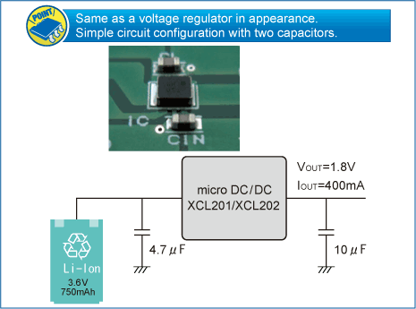
The XCL201 series is a synchronous step-down micro DC/DC converter which integrates an inductor and a control IC in one tiny package (2.5mm×2.0mm, h=1.0mm). A stable power supply with an output current of 400mA is configured using only two capacitors connected externally.
Operating voltage range is from 2.0V to 6.0V. Output voltage is internally set in a range from 0.8V to 4.0V in increments of 0.05V. The device is operated by 1.2MHz, and includes 0.42ΩP-ch driver transistor and 0.52 Ω N-ch switching transistor.
During stand-by, the device is shutdown to reduce current consumption to as low as 1.0μA or less. With the built-in UVLO (Under Voltage Lock Out) function, the internal driver transistor is forced OFF when input voltage becomes 1.4V or lower. The series provide short-time turn-on by the soft start function internally set in 0.25 ms (TYP). The series integrate CL auto discharge function which enables the electric charge stored at the output capacitor CL to be discharged via the internal auto-discharge switch located between the LX and VSS pins. When the devices enter stand-by mode, output voltage quickly returns to the VSS level as a result of this function.
Feature
| Input Voltage Range | 2.0V~6.0V |
| Output Voltage Range | 0.8V~4.0V(Accuracy ±2.0%) |
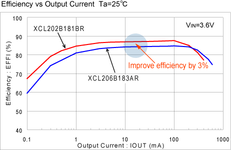
| High Efficiency(VOUT=1.8V) | 92%(VIN=4.2V,VOUT=3.3V) |
| Output Current | 400mA |
| Oscillation Frequency | 1.2MHz(Accuracy ±15%) |
| Maximum Duty Cycle | 100% |
| Capacitor | Low ESR Ceramic |
| Protection Circuits | Current Limiter Circuit Built-In,(Constant Current & Latching) |
| Control Methods | PWM |
| CE Function | CL High Speed Auto Discharge |
Typical Application Circuit


Quality Reports
Technical Document
Packages
| Package | Number of Pins | Pcs/Reel | Package Size(mm) |
|---|---|---|---|
| CL-2025-02 | 6 | 3,000 | 2.0 x 2.5 x 1.04 |
XCL201 Series Part Numbers
| Part number | Sample | Functions selection | Output Voltage | Oscillation Frequency | Packages | EDA | Online Store |
|---|---|---|---|---|---|---|---|
|
|
|
|
|
|
|
|
|
| XCL201B081ER-G | CL Auto Discharge, High Speed Soft-start | 0.8V | 1.2MHz | CL-2025-02 |
|
||
| XCL201B091ER-G | CL Auto Discharge, High Speed Soft-start | 0.9V | 1.2MHz | CL-2025-02 |
|
||
| XCL201B0L1ER-G | CL Auto Discharge, High Speed Soft-start | 0.85V | 1.2MHz | CL-2025-02 |
|
||
| XCL201B0M1ER-G | CL Auto Discharge, High Speed Soft-start | 0.95V | 1.2MHz | CL-2025-02 |
|
||
| XCL201B101ER-G | CL Auto Discharge, High Speed Soft-start | 1.0V | 1.2MHz | CL-2025-02 |
|
||
| XCL201B111ER-G | CL Auto Discharge, High Speed Soft-start | 1.1V | 1.2MHz | CL-2025-02 |
|
||
| XCL201B121ER-G | CL Auto Discharge, High Speed Soft-start | 1.2V | 1.2MHz | CL-2025-02 |
|
||
| XCL201B131ER-G | CL Auto Discharge, High Speed Soft-start | 1.3V | 1.2MHz | CL-2025-02 |
|
||
| XCL201B141ER-G | CL Auto Discharge, High Speed Soft-start | 1.4V | 1.2MHz | CL-2025-02 |
|
||
| XCL201B151ER-G | CL Auto Discharge, High Speed Soft-start | 1.5V | 1.2MHz | CL-2025-02 |
|
||
| XCL201B161ER-G | CL Auto Discharge, High Speed Soft-start | 1.6V | 1.2MHz | CL-2025-02 |
|
||
| XCL201B171ER-G | CL Auto Discharge, High Speed Soft-start | 1.7V | 1.2MHz | CL-2025-02 |
|
||
| XCL201B181ER-G | CL Auto Discharge, High Speed Soft-start | 1.8V | 1.2MHz | CL-2025-02 |
|
||
| XCL201B191ER-G | CL Auto Discharge, High Speed Soft-start | 1.9V | 1.2MHz | CL-2025-02 |
|
||
| XCL201B1A1ER-G | CL Auto Discharge, High Speed Soft-start | 1.05V | 1.2MHz | CL-2025-02 |
|
||
| XCL201B1B1ER-G | CL Auto Discharge, High Speed Soft-start | 1.15V | 1.2MHz | CL-2025-02 |
|
||
| XCL201B1C1ER-G | CL Auto Discharge, High Speed Soft-start | 1.25V | 1.2MHz | CL-2025-02 |
|
||
| XCL201B1D1ER-G | CL Auto Discharge, High Speed Soft-start | 1.35V | 1.2MHz | CL-2025-02 |
|
||
| XCL201B1E1ER-G | CL Auto Discharge, High Speed Soft-start | 1.45V | 1.2MHz | CL-2025-02 |
|
||
| XCL201B1F1ER-G | CL Auto Discharge, High Speed Soft-start | 1.55V | 1.2MHz | CL-2025-02 |
|
||
| XCL201B1H1ER-G | CL Auto Discharge, High Speed Soft-start | 1.65V | 1.2MHz | CL-2025-02 |
|
||
| XCL201B1K1ER-G | CL Auto Discharge, High Speed Soft-start | 1.75V | 1.2MHz | CL-2025-02 |
|
||
| XCL201B1L1ER-G | CL Auto Discharge, High Speed Soft-start | 1.85V | 1.2MHz | CL-2025-02 |
|
||
| XCL201B1M1ER-G | CL Auto Discharge, High Speed Soft-start | 1.95V | 1.2MHz | CL-2025-02 |
|
||
| XCL201B201ER-G | CL Auto Discharge, High Speed Soft-start | 2.0V | 1.2MHz | CL-2025-02 |
|
||
| XCL201B211ER-G | CL Auto Discharge, High Speed Soft-start | 2.1V | 1.2MHz | CL-2025-02 |
|
||
| XCL201B221ER-G | CL Auto Discharge, High Speed Soft-start | 2.2V | 1.2MHz | CL-2025-02 |
|
||
| XCL201B231ER-G | CL Auto Discharge, High Speed Soft-start | 2.3V | 1.2MHz | CL-2025-02 |
|
||
| XCL201B241ER-G | CL Auto Discharge, High Speed Soft-start | 2.4V | 1.2MHz | CL-2025-02 |
|
||
| XCL201B251ER-G | CL Auto Discharge, High Speed Soft-start | 2.5V | 1.2MHz | CL-2025-02 |
|
||
| XCL201B261ER-G | CL Auto Discharge, High Speed Soft-start | 2.6V | 1.2MHz | CL-2025-02 |
|
||
| XCL201B271ER-G | CL Auto Discharge, High Speed Soft-start | 2.7V | 1.2MHz | CL-2025-02 |
|
||
| XCL201B281ER-G | CL Auto Discharge, High Speed Soft-start | 2.8V | 1.2MHz | CL-2025-02 |
|
||
| XCL201B291ER-G | CL Auto Discharge, High Speed Soft-start | 2.9V | 1.2MHz | CL-2025-02 |
|
||
| XCL201B2A1ER-G | CL Auto Discharge, High Speed Soft-start | 2.05V | 1.2MHz | CL-2025-02 |
|
||
| XCL201B2B1ER-G | CL Auto Discharge, High Speed Soft-start | 2.15V | 1.2MHz | CL-2025-02 |
|
||
| XCL201B2C1ER-G | CL Auto Discharge, High Speed Soft-start | 2.25V | 1.2MHz | CL-2025-02 |
|
||
| XCL201B2D1ER-G | CL Auto Discharge, High Speed Soft-start | 2.35V | 1.2MHz | CL-2025-02 |
|
||
| XCL201B2E1ER-G | CL Auto Discharge, High Speed Soft-start | 2.45V | 1.2MHz | CL-2025-02 |
|
||
| XCL201B2F1ER-G | CL Auto Discharge, High Speed Soft-start | 2.55V | 1.2MHz | CL-2025-02 |
|
||
| XCL201B2H1ER-G | CL Auto Discharge, High Speed Soft-start | 2.65V | 1.2MHz | CL-2025-02 |
|
||
| XCL201B2K1ER-G | CL Auto Discharge, High Speed Soft-start | 2.75V | 1.2MHz | CL-2025-02 |
|
||
| XCL201B2L1ER-G | CL Auto Discharge, High Speed Soft-start | 2.85V | 1.2MHz | CL-2025-02 |
|
||
| XCL201B2M1ER-G | CL Auto Discharge, High Speed Soft-start | 2.95V | 1.2MHz | CL-2025-02 |
|
||
| XCL201B301ER-G | CL Auto Discharge, High Speed Soft-start | 3.0V | 1.2MHz | CL-2025-02 |
|
||
| XCL201B311ER-G | CL Auto Discharge, High Speed Soft-start | 3.1V | 1.2MHz | CL-2025-02 |
|
||
| XCL201B321ER-G | CL Auto Discharge, High Speed Soft-start | 3.2V | 1.2MHz | CL-2025-02 |
|
||
| XCL201B331ER-G | CL Auto Discharge, High Speed Soft-start | 3.3V | 1.2MHz | CL-2025-02 |
|
||
| XCL201B341ER-G | CL Auto Discharge, High Speed Soft-start | 3.4V | 1.2MHz | CL-2025-02 |
|
||
| XCL201B351ER-G | CL Auto Discharge, High Speed Soft-start | 3.5V | 1.2MHz | CL-2025-02 |
|
||
| XCL201B361ER-G | CL Auto Discharge, High Speed Soft-start | 3.6V | 1.2MHz | CL-2025-02 |
|
||
| XCL201B371ER-G | CL Auto Discharge, High Speed Soft-start | 3.7V | 1.2MHz | CL-2025-02 |
|
||
| XCL201B381ER-G | CL Auto Discharge, High Speed Soft-start | 3.8V | 1.2MHz | CL-2025-02 |
|
||
| XCL201B391ER-G | CL Auto Discharge, High Speed Soft-start | 3.9V | 1.2MHz | CL-2025-02 |
|
||
| XCL201B3A1ER-G | CL Auto Discharge, High Speed Soft-start | 3.05V | 1.2MHz | CL-2025-02 |
|
||
| XCL201B3B1ER-G | CL Auto Discharge, High Speed Soft-start | 3.15V | 1.2MHz | CL-2025-02 |
|
||
| XCL201B3C1ER-G | CL Auto Discharge, High Speed Soft-start | 3.25V | 1.2MHz | CL-2025-02 |
|
||
| XCL201B3D1ER-G | CL Auto Discharge, High Speed Soft-start | 3.35V | 1.2MHz | CL-2025-02 |
|
||
| XCL201B3E1ER-G | CL Auto Discharge, High Speed Soft-start | 3.45V | 1.2MHz | CL-2025-02 |
|
||
| XCL201B3F1ER-G | CL Auto Discharge, High Speed Soft-start | 3.55V | 1.2MHz | CL-2025-02 |
|
||
| XCL201B3H1ER-G | CL Auto Discharge, High Speed Soft-start | 3.65V | 1.2MHz | CL-2025-02 |
|
||
| XCL201B3K1ER-G | CL Auto Discharge, High Speed Soft-start | 3.75V | 1.2MHz | CL-2025-02 |
|
||
| XCL201B3L1ER-G | CL Auto Discharge, High Speed Soft-start | 3.85V | 1.2MHz | CL-2025-02 |
|
||
| XCL201B3M1ER-G | CL Auto Discharge, High Speed Soft-start | 3.95V | 1.2MHz | CL-2025-02 |
|
||
| XCL201B401ER-G | CL Auto Discharge, High Speed Soft-start | 4.0V | 1.2MHz | CL-2025-02 |
|
Inquiries About XCL201
Please wait for a while until the form is displaying.
If the form is not displaying, please contact us from inquiry form.