Dual Output Step-Up/Inverting DC/DC Converter
The XC9519 series is a 2 channel (step-up and inverting) DC/DC converter IC. One DC/DC converter is a step-up DC/DC and the other is an inverting DC/DC converter. The step-up converter compares a built-in reference voltage 1.0V to the FBP voltage (±1.5%) and a positive output voltage can be set freely with the external components up to 18V. The inverting DC/DC converter compares a difference between a reference voltage and the FBN voltage (±1.5%) to the GND, then a negative output voltage can be set until -15V with the external components.
With a 1.2MHz frequency, the size of the external components can be reduced. As for operation mode, the device can be selected to use PWM control or automatic PWM/PFM switching control by the MODE pin. In the automatic PWM/PFM switching control mode, control switches from PWM to PFM during light loads. The series is highly efficient from light loads through to large output currents. In the PWM control mode, noise is easily reduced since the frequency is fixed. The control mode can be selected for each application. The soft start and current control functions are internally optimized.
During stand-by, all circuits in the IC are shutdown to reduce current consumption to as low as 1.0μA or less. The device includes a gate control pin for the P-channel MOSFET which is used for a load disconnection at the stand-by mode. The GAINP and GAINN pins are used for loop compensation in order to optimize load transient response. With the built-in UVLO (Under Voltage Lock Out) function, the internal driver transistor is forced OFF when input voltage becomes 2.2V or lower.
Feature
| Input Voltage | 2.7V~5.5V |
| Output Current | 500mA@VIN=3.7V,VOUTP=5.0V,VOUTN=-5.0V |
| Positive Output Voltage | 4.0V~18.0V(Accuracy ±1.5%@25℃) |
| Negative Output Voltage | -15.0V~-4.0V(Accuracy ±1.5%@25℃) |
| Oscillation Frequency | 1.2MHz |
| Soft-Start Circuit Built-In: | Step-Up DC/DC converter 2.5ms (TYP.) Inverting DC/DC converter 2.2ms (TYP.) |
| Protection Circuits | Over Current Limit (Integral Latching),Short Circuit Protection Latching,UVLO,Thermal Shut Down,Over Voltage Protection |
| Function Addition | Control Pin,Load disconnect Pin,Phase Compensation Pin,Ceramic Capacitor Compatible |
| Operating Ambient Temperature | -40℃~+85℃ |
| Environmentally Friendly | EU RoHS compliant, Pb free |
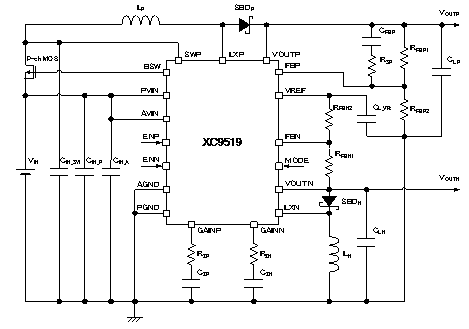
Typical Application Circuit
Quality Reports
Technical Document
Packages
| Package | Number of Pins | Pcs/Reel | Package Size(mm) |
|---|---|---|---|
| QFN-24 | 24 | 1,000 | 4.0 x 4.0 x 0.8 |
XC9519 Series Part Numbers
| Part number | Sample | Package | EDA | Online Store |
|---|---|---|---|---|
|
|
|
|
|
|
|
XC9519A12AZR-G |
QFN-24 |
|
Inquiries About XC9519
Please wait for a while until the form is displaying.
If the form is not displaying, please contact us from inquiry form.