200mA High Speed LDO Voltage Regulator with Built-in Inrush Current Protection
The XC6233 series is a 200mA high speed LDO regulator that features high accurate, high ripple rejection and low dropout. The series consists of a voltage reference, an error amplifier, a driver transistor, a current limiter, a phase compensation circuit and an inrush current protection circuit. The output voltage is selectable in 0.05V increments (±1.0%) within the range of 1.2V to 3.6V using laser trimming technologies. The CE function enables the circuit to be in stand-by mode by inputting low level signal. In the stand-by mode, the series enables the electric charge at the output capacitor CL to be discharged via the internal switch, and as a result the VOUT pin quickly returns to the Low level. he series is also compatible with low ESR ceramic capacitors, which provides stable output voltage. This stability can be maintained even during load fluctuations due to the excellent transient response.
The over current protection circuit is built-in. The protection circuit will operate when the output current reaches current limit level.
Feature
| MaximumOutput Current | 200mA |
| Input Voltage Range | 1.7V~5.5V |
| Output Voltage Range | 1.2V~3.6V(±1%)0.05V increments |
| Dropout Voltage | 240mV@IOUT=200mA(VOUT=3.0V) |
| Low Quiescent Current | 45μA(TYP.) |
| Stand-by Current | Less than 0.1μA |
| High Ripple Rejection: | 75dB@1kHz |
| CE Function | Active High、CL High Speed Auto Discharge |
| Protection Circuits | Current Limit255mA(TYP.) Short Circuit Protection 60mA(TYP.) |
| Low ESR Capacitor | Low ESR Ceramic Capacitor 1.0μF |
| Operating Ambient Temperature | -40℃~+85℃ |
| Environmentally Friendly | EU RoHS compliant, Pb free |
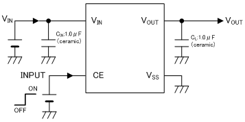
Typical Application Circuit
Quality Reports
Technical Document
- Gerberfile:XC6233 USPQ-4B04
- Gerberfile:XC6233 SOT-25
- Gerberfile:XC6233 SSOT-24
- Gerberfile:XC6233 USP-4
- Leaflet
- Product Overview
Packages
XC6233 Series Part Numbers
| Part number | Sample | Type | Output Voltage | Output Voltage Accuracy | Packages | EDA | Online Store |
|---|---|---|---|---|---|---|---|
|
|
|
|
|
|
|
|
|
| XC6233H1219R-G | With Inrush Current Protection, With CE Pull-down, With CL discharge | 1.2V | Output voltage {○.○0v} (the 2nd decimal place is “0”) | USPQ-4B04 |
|
||
| XC6233H1319R-G | With Inrush Current Protection, With CE Pull-down, With CL discharge | 1.3V | Output voltage {○.○0v} (the 2nd decimal place is “0”) | USPQ-4B04 |
|
||
| XC6233H1419R-G | With Inrush Current Protection, With CE Pull-down, With CL discharge | 1.4V | Output voltage {○.○0v} (the 2nd decimal place is “0”) | USPQ-4B04 |
|
||
| XC6233H1519R-G | With Inrush Current Protection, With CE Pull-down, With CL discharge | 1.5V | Output voltage {○.○0v} (the 2nd decimal place is “0”) | USPQ-4B04 |
|
||
| XC6233H1619R-G | With Inrush Current Protection, With CE Pull-down, With CL discharge | 1.6V | Output voltage {○.○0v} (the 2nd decimal place is “0”) | USPQ-4B04 |
|
||
| XC6233H1719R-G | With Inrush Current Protection, With CE Pull-down, With CL discharge | 1.7V | Output voltage {○.○0v} (the 2nd decimal place is “0”) | USPQ-4B04 |
|
||
| XC6233H1819R-G | With Inrush Current Protection, With CE Pull-down, With CL discharge | 1.8V | Output voltage {○.○0v} (the 2nd decimal place is “0”) | USPQ-4B04 |
|
||
| XC6233H1919R-G | With Inrush Current Protection, With CE Pull-down, With CL discharge | 1.9V | Output voltage {○.○0v} (the 2nd decimal place is “0”) | USPQ-4B04 |
|
||
| XC6233H2019R-G | With Inrush Current Protection, With CE Pull-down, With CL discharge | 2.0V | Output voltage {○.○0v} (the 2nd decimal place is “0”) | USPQ-4B04 |
|
||
| XC6233H2119R-G | With Inrush Current Protection, With CE Pull-down, With CL discharge | 2.1V | Output voltage {○.○0v} (the 2nd decimal place is “0”) | USPQ-4B04 |
|
||
| XC6233H2219R-G | With Inrush Current Protection, With CE Pull-down, With CL discharge | 2.2V | Output voltage {○.○0v} (the 2nd decimal place is “0”) | USPQ-4B04 |
|
||
| XC6233H2319R-G | With Inrush Current Protection, With CE Pull-down, With CL discharge | 2.3V | Output voltage {○.○0v} (the 2nd decimal place is “0”) | USPQ-4B04 |
|
||
| XC6233H2419R-G | With Inrush Current Protection, With CE Pull-down, With CL discharge | 2.4V | Output voltage {○.○0v} (the 2nd decimal place is “0”) | USPQ-4B04 |
|
||
| XC6233H2519R-G | With Inrush Current Protection, With CE Pull-down, With CL discharge | 2.5V | Output voltage {○.○0v} (the 2nd decimal place is “0”) | USPQ-4B04 |
|
||
| XC6233H2619R-G | With Inrush Current Protection, With CE Pull-down, With CL discharge | 2.6V | Output voltage {○.○0v} (the 2nd decimal place is “0”) | USPQ-4B04 |
|
||
| XC6233H2719R-G | With Inrush Current Protection, With CE Pull-down, With CL discharge | 2.7V | Output voltage {○.○0v} (the 2nd decimal place is “0”) | USPQ-4B04 |
|
||
| XC6233H2819R-G | With Inrush Current Protection, With CE Pull-down, With CL discharge | 2.8V | Output voltage {○.○0v} (the 2nd decimal place is “0”) | USPQ-4B04 |
|
||
| XC6233H2919R-G | With Inrush Current Protection, With CE Pull-down, With CL discharge | 2.9V | Output voltage {○.○0v} (the 2nd decimal place is “0”) | USPQ-4B04 |
|
||
| XC6233H3019R-G | With Inrush Current Protection, With CE Pull-down, With CL discharge | 3.0V | Output voltage {○.○0v} (the 2nd decimal place is “0”) | USPQ-4B04 |
|
||
| XC6233H3119R-G | With Inrush Current Protection, With CE Pull-down, With CL discharge | 3.1V | Output voltage {○.○0v} (the 2nd decimal place is “0”) | USPQ-4B04 |
|
||
| XC6233H3219R-G | With Inrush Current Protection, With CE Pull-down, With CL discharge | 3.2V | Output voltage {○.○0v} (the 2nd decimal place is “0”) | USPQ-4B04 |
|
||
| XC6233H3319R-G | With Inrush Current Protection, With CE Pull-down, With CL discharge | 3.3V | Output voltage {○.○0v} (the 2nd decimal place is “0”) | USPQ-4B04 |
|
||
| XC6233H3419R-G | With Inrush Current Protection, With CE Pull-down, With CL discharge | 3.4V | Output voltage {○.○0v} (the 2nd decimal place is “0”) | USPQ-4B04 |
|
||
| XC6233H3519R-G | With Inrush Current Protection, With CE Pull-down, With CL discharge | 3.5V | Output voltage {○.○0v} (the 2nd decimal place is “0”) | USPQ-4B04 |
|
||
| XC6233H3619R-G | With Inrush Current Protection, With CE Pull-down, With CL discharge | 3.6V | Output voltage {○.○0v} (the 2nd decimal place is “0”) | USPQ-4B04 |
|
||
| XC6233H12B9R-G | With Inrush Current Protection, With CE Pull-down, With CL discharge | 1.2V | Output voltage {○.○5v} (the 2nd decimal place is “5”) | USPQ-4B04 |
|
||
| XC6233H13B9R-G | With Inrush Current Protection, With CE Pull-down, With CL discharge | 1.3V | Output voltage {○.○5v} (the 2nd decimal place is “5”) | USPQ-4B04 |
|
||
| XC6233H14B9R-G | With Inrush Current Protection, With CE Pull-down, With CL discharge | 1.4V | Output voltage {○.○5v} (the 2nd decimal place is “5”) | USPQ-4B04 |
|
||
| XC6233H15B9R-G | With Inrush Current Protection, With CE Pull-down, With CL discharge | 1.5V | Output voltage {○.○5v} (the 2nd decimal place is “5”) | USPQ-4B04 |
|
||
| XC6233H16B9R-G | With Inrush Current Protection, With CE Pull-down, With CL discharge | 1.6V | Output voltage {○.○5v} (the 2nd decimal place is “5”) | USPQ-4B04 |
|
||
| XC6233H17B9R-G | With Inrush Current Protection, With CE Pull-down, With CL discharge | 1.7V | Output voltage {○.○5v} (the 2nd decimal place is “5”) | USPQ-4B04 |
|
||
| XC6233H18B9R-G | With Inrush Current Protection, With CE Pull-down, With CL discharge | 1.8V | Output voltage {○.○5v} (the 2nd decimal place is “5”) | USPQ-4B04 |
|
||
| XC6233H19B9R-G | With Inrush Current Protection, With CE Pull-down, With CL discharge | 1.9V | Output voltage {○.○5v} (the 2nd decimal place is “5”) | USPQ-4B04 |
|
||
| XC6233H20B9R-G | With Inrush Current Protection, With CE Pull-down, With CL discharge | 2.0V | Output voltage {○.○5v} (the 2nd decimal place is “5”) | USPQ-4B04 |
|
||
| XC6233H21B9R-G | With Inrush Current Protection, With CE Pull-down, With CL discharge | 2.1V | Output voltage {○.○5v} (the 2nd decimal place is “5”) | USPQ-4B04 |
|
||
| XC6233H22B9R-G | With Inrush Current Protection, With CE Pull-down, With CL discharge | 2.2V | Output voltage {○.○5v} (the 2nd decimal place is “5”) | USPQ-4B04 |
|
||
| XC6233H23B9R-G | With Inrush Current Protection, With CE Pull-down, With CL discharge | 2.3V | Output voltage {○.○5v} (the 2nd decimal place is “5”) | USPQ-4B04 |
|
||
| XC6233H24B9R-G | With Inrush Current Protection, With CE Pull-down, With CL discharge | 2.4V | Output voltage {○.○5v} (the 2nd decimal place is “5”) | USPQ-4B04 |
|
||
| XC6233H25B9R-G | With Inrush Current Protection, With CE Pull-down, With CL discharge | 2.5V | Output voltage {○.○5v} (the 2nd decimal place is “5”) | USPQ-4B04 |
|
||
| XC6233H26B9R-G | With Inrush Current Protection, With CE Pull-down, With CL discharge | 2.6V | Output voltage {○.○5v} (the 2nd decimal place is “5”) | USPQ-4B04 |
|
||
| XC6233H27B9R-G | With Inrush Current Protection, With CE Pull-down, With CL discharge | 2.7V | Output voltage {○.○5v} (the 2nd decimal place is “5”) | USPQ-4B04 |
|
||
| XC6233H28B9R-G | With Inrush Current Protection, With CE Pull-down, With CL discharge | 2.8V | Output voltage {○.○5v} (the 2nd decimal place is “5”) | USPQ-4B04 |
|
||
| XC6233H29B9R-G | With Inrush Current Protection, With CE Pull-down, With CL discharge | 2.9V | Output voltage {○.○5v} (the 2nd decimal place is “5”) | USPQ-4B04 |
|
||
| XC6233H30B9R-G | With Inrush Current Protection, With CE Pull-down, With CL discharge | 3.0V | Output voltage {○.○5v} (the 2nd decimal place is “5”) | USPQ-4B04 |
|
||
| XC6233H31B9R-G | With Inrush Current Protection, With CE Pull-down, With CL discharge | 3.1V | Output voltage {○.○5v} (the 2nd decimal place is “5”) | USPQ-4B04 |
|
||
| XC6233H32B9R-G | With Inrush Current Protection, With CE Pull-down, With CL discharge | 3.2V | Output voltage {○.○5v} (the 2nd decimal place is “5”) | USPQ-4B04 |
|
||
| XC6233H33B9R-G | With Inrush Current Protection, With CE Pull-down, With CL discharge | 3.3V | Output voltage {○.○5v} (the 2nd decimal place is “5”) | USPQ-4B04 |
|
||
| XC6233H34B9R-G | With Inrush Current Protection, With CE Pull-down, With CL discharge | 3.4V | Output voltage {○.○5v} (the 2nd decimal place is “5”) | USPQ-4B04 |
|
||
| XC6233H35B9R-G | With Inrush Current Protection, With CE Pull-down, With CL discharge | 3.5V | Output voltage {○.○5v} (the 2nd decimal place is “5”) | USPQ-4B04 |
|
||
| XC6233H121GR-G | With Inrush Current Protection, With CE Pull-down, With CL discharge | 1.2V | Output voltage {○.○0v} (the 2nd decimal place is “0”) | USP-4 |
|
||
| XC6233H131GR-G | With Inrush Current Protection, With CE Pull-down, With CL discharge | 1.3V | Output voltage {○.○0v} (the 2nd decimal place is “0”) | USP-4 |
|
||
| XC6233H141GR-G | With Inrush Current Protection, With CE Pull-down, With CL discharge | 1.4V | Output voltage {○.○0v} (the 2nd decimal place is “0”) | USP-4 |
|
||
| XC6233H151GR-G | With Inrush Current Protection, With CE Pull-down, With CL discharge | 1.5V | Output voltage {○.○0v} (the 2nd decimal place is “0”) | USP-4 |
|
||
| XC6233H161GR-G | With Inrush Current Protection, With CE Pull-down, With CL discharge | 1.6V | Output voltage {○.○0v} (the 2nd decimal place is “0”) | USP-4 |
|
||
| XC6233H171GR-G | With Inrush Current Protection, With CE Pull-down, With CL discharge | 1.7V | Output voltage {○.○0v} (the 2nd decimal place is “0”) | USP-4 |
|
||
| XC6233H181GR-G | With Inrush Current Protection, With CE Pull-down, With CL discharge | 1.8V | Output voltage {○.○0v} (the 2nd decimal place is “0”) | USP-4 |
|
||
| XC6233H191GR-G | With Inrush Current Protection, With CE Pull-down, With CL discharge | 1.9V | Output voltage {○.○0v} (the 2nd decimal place is “0”) | USP-4 |
|
||
| XC6233H201GR-G | With Inrush Current Protection, With CE Pull-down, With CL discharge | 2.0V | Output voltage {○.○0v} (the 2nd decimal place is “0”) | USP-4 |
|
||
| XC6233H211GR-G | With Inrush Current Protection, With CE Pull-down, With CL discharge | 2.1V | Output voltage {○.○0v} (the 2nd decimal place is “0”) | USP-4 |
|
||
| XC6233H221GR-G | With Inrush Current Protection, With CE Pull-down, With CL discharge | 2.2V | Output voltage {○.○0v} (the 2nd decimal place is “0”) | USP-4 |
|
||
| XC6233H231GR-G | With Inrush Current Protection, With CE Pull-down, With CL discharge | 2.3V | Output voltage {○.○0v} (the 2nd decimal place is “0”) | USP-4 |
|
||
| XC6233H241GR-G | With Inrush Current Protection, With CE Pull-down, With CL discharge | 2.4V | Output voltage {○.○0v} (the 2nd decimal place is “0”) | USP-4 |
|
||
| XC6233H251GR-G | With Inrush Current Protection, With CE Pull-down, With CL discharge | 2.5V | Output voltage {○.○0v} (the 2nd decimal place is “0”) | USP-4 |
|
||
| XC6233H261GR-G | With Inrush Current Protection, With CE Pull-down, With CL discharge | 2.6V | Output voltage {○.○0v} (the 2nd decimal place is “0”) | USP-4 |
|
||
| XC6233H271GR-G | With Inrush Current Protection, With CE Pull-down, With CL discharge | 2.7V | Output voltage {○.○0v} (the 2nd decimal place is “0”) | USP-4 |
|
||
| XC6233H281GR-G | With Inrush Current Protection, With CE Pull-down, With CL discharge | 2.8V | Output voltage {○.○0v} (the 2nd decimal place is “0”) | USP-4 |
|
||
| XC6233H291GR-G | With Inrush Current Protection, With CE Pull-down, With CL discharge | 2.9V | Output voltage {○.○0v} (the 2nd decimal place is “0”) | USP-4 |
|
||
| XC6233H301GR-G | With Inrush Current Protection, With CE Pull-down, With CL discharge | 3.0V | Output voltage {○.○0v} (the 2nd decimal place is “0”) | USP-4 |
|
||
| XC6233H311GR-G | With Inrush Current Protection, With CE Pull-down, With CL discharge | 3.1V | Output voltage {○.○0v} (the 2nd decimal place is “0”) | USP-4 |
|
||
| XC6233H321GR-G | With Inrush Current Protection, With CE Pull-down, With CL discharge | 3.2V | Output voltage {○.○0v} (the 2nd decimal place is “0”) | USP-4 |
|
||
| XC6233H331GR-G | With Inrush Current Protection, With CE Pull-down, With CL discharge | 3.3V | Output voltage {○.○0v} (the 2nd decimal place is “0”) | USP-4 |
|
||
| XC6233H341GR-G | With Inrush Current Protection, With CE Pull-down, With CL discharge | 3.4V | Output voltage {○.○0v} (the 2nd decimal place is “0”) | USP-4 |
|
||
| XC6233H351GR-G | With Inrush Current Protection, With CE Pull-down, With CL discharge | 3.5V | Output voltage {○.○0v} (the 2nd decimal place is “0”) | USP-4 |
|
||
| XC6233H361GR-G | With Inrush Current Protection, With CE Pull-down, With CL discharge | 3.6V | Output voltage {○.○0v} (the 2nd decimal place is “0”) | USP-4 |
|
||
| XC6233H12BGR-G | With Inrush Current Protection, With CE Pull-down, With CL discharge | 1.2V | Output voltage {○.○5v} (the 2nd decimal place is “5”) | USP-4 |
|
||
| XC6233H13BGR-G | With Inrush Current Protection, With CE Pull-down, With CL discharge | 1.3V | Output voltage {○.○5v} (the 2nd decimal place is “5”) | USP-4 |
|
||
| XC6233H14BGR-G | With Inrush Current Protection, With CE Pull-down, With CL discharge | 1.4V | Output voltage {○.○5v} (the 2nd decimal place is “5”) | USP-4 |
|
||
| XC6233H15BGR-G | With Inrush Current Protection, With CE Pull-down, With CL discharge | 1.5V | Output voltage {○.○5v} (the 2nd decimal place is “5”) | USP-4 |
|
||
| XC6233H16BGR-G | With Inrush Current Protection, With CE Pull-down, With CL discharge | 1.6V | Output voltage {○.○5v} (the 2nd decimal place is “5”) | USP-4 |
|
||
| XC6233H17BGR-G | With Inrush Current Protection, With CE Pull-down, With CL discharge | 1.7V | Output voltage {○.○5v} (the 2nd decimal place is “5”) | USP-4 |
|
||
| XC6233H18BGR-G | With Inrush Current Protection, With CE Pull-down, With CL discharge | 1.8V | Output voltage {○.○5v} (the 2nd decimal place is “5”) | USP-4 |
|
||
| XC6233H19BGR-G | With Inrush Current Protection, With CE Pull-down, With CL discharge | 1.9V | Output voltage {○.○5v} (the 2nd decimal place is “5”) | USP-4 |
|
||
| XC6233H20BGR-G | With Inrush Current Protection, With CE Pull-down, With CL discharge | 2.0V | Output voltage {○.○5v} (the 2nd decimal place is “5”) | USP-4 |
|
||
| XC6233H21BGR-G | With Inrush Current Protection, With CE Pull-down, With CL discharge | 2.1V | Output voltage {○.○5v} (the 2nd decimal place is “5”) | USP-4 |
|
||
| XC6233H22BGR-G | With Inrush Current Protection, With CE Pull-down, With CL discharge | 2.2V | Output voltage {○.○5v} (the 2nd decimal place is “5”) | USP-4 |
|
||
| XC6233H23BGR-G | With Inrush Current Protection, With CE Pull-down, With CL discharge | 2.3V | Output voltage {○.○5v} (the 2nd decimal place is “5”) | USP-4 |
|
||
| XC6233H24BGR-G | With Inrush Current Protection, With CE Pull-down, With CL discharge | 2.4V | Output voltage {○.○5v} (the 2nd decimal place is “5”) | USP-4 |
|
||
| XC6233H25BGR-G | With Inrush Current Protection, With CE Pull-down, With CL discharge | 2.5V | Output voltage {○.○5v} (the 2nd decimal place is “5”) | USP-4 |
|
||
| XC6233H26BGR-G | With Inrush Current Protection, With CE Pull-down, With CL discharge | 2.6V | Output voltage {○.○5v} (the 2nd decimal place is “5”) | USP-4 |
|
||
| XC6233H27BGR-G | With Inrush Current Protection, With CE Pull-down, With CL discharge | 2.7V | Output voltage {○.○5v} (the 2nd decimal place is “5”) | USP-4 |
|
||
| XC6233H28BGR-G | With Inrush Current Protection, With CE Pull-down, With CL discharge | 2.8V | Output voltage {○.○5v} (the 2nd decimal place is “5”) | USP-4 |
|
||
| XC6233H29BGR-G | With Inrush Current Protection, With CE Pull-down, With CL discharge | 2.9V | Output voltage {○.○5v} (the 2nd decimal place is “5”) | USP-4 |
|
||
| XC6233H30BGR-G | With Inrush Current Protection, With CE Pull-down, With CL discharge | 3.0V | Output voltage {○.○5v} (the 2nd decimal place is “5”) | USP-4 |
|
||
| XC6233H31BGR-G | With Inrush Current Protection, With CE Pull-down, With CL discharge | 3.1V | Output voltage {○.○5v} (the 2nd decimal place is “5”) | USP-4 |
|
||
| XC6233H32BGR-G | With Inrush Current Protection, With CE Pull-down, With CL discharge | 3.2V | Output voltage {○.○5v} (the 2nd decimal place is “5”) | USP-4 |
|
||
| XC6233H33BGR-G | With Inrush Current Protection, With CE Pull-down, With CL discharge | 3.3V | Output voltage {○.○5v} (the 2nd decimal place is “5”) | USP-4 |
|
||
| XC6233H34BGR-G | With Inrush Current Protection, With CE Pull-down, With CL discharge | 3.4V | Output voltage {○.○5v} (the 2nd decimal place is “5”) | USP-4 |
|
||
| XC6233H35BGR-G | With Inrush Current Protection, With CE Pull-down, With CL discharge | 3.5V | Output voltage {○.○5v} (the 2nd decimal place is “5”) | USP-4 |
|
||
| XC6233H121NR-G | With Inrush Current Protection, With CE Pull-down, With CL discharge | 1.2V | Output voltage {○.○0v} (the 2nd decimal place is “0”) | SSOT-24 |
|
||
| XC6233H131NR-G | With Inrush Current Protection, With CE Pull-down, With CL discharge | 1.3V | Output voltage {○.○0v} (the 2nd decimal place is “0”) | SSOT-24 |
|
||
| XC6233H141NR-G | With Inrush Current Protection, With CE Pull-down, With CL discharge | 1.4V | Output voltage {○.○0v} (the 2nd decimal place is “0”) | SSOT-24 |
|
||
| XC6233H151NR-G | With Inrush Current Protection, With CE Pull-down, With CL discharge | 1.5V | Output voltage {○.○0v} (the 2nd decimal place is “0”) | SSOT-24 |
|
||
| XC6233H161NR-G | With Inrush Current Protection, With CE Pull-down, With CL discharge | 1.6V | Output voltage {○.○0v} (the 2nd decimal place is “0”) | SSOT-24 |
|
||
| XC6233H171NR-G | With Inrush Current Protection, With CE Pull-down, With CL discharge | 1.7V | Output voltage {○.○0v} (the 2nd decimal place is “0”) | SSOT-24 |
|
||
| XC6233H181NR-G | With Inrush Current Protection, With CE Pull-down, With CL discharge | 1.8V | Output voltage {○.○0v} (the 2nd decimal place is “0”) | SSOT-24 |
|
||
| XC6233H191NR-G | With Inrush Current Protection, With CE Pull-down, With CL discharge | 1.9V | Output voltage {○.○0v} (the 2nd decimal place is “0”) | SSOT-24 |
|
||
| XC6233H201NR-G | With Inrush Current Protection, With CE Pull-down, With CL discharge | 2.0V | Output voltage {○.○0v} (the 2nd decimal place is “0”) | SSOT-24 |
|
||
| XC6233H211NR-G | With Inrush Current Protection, With CE Pull-down, With CL discharge | 2.1V | Output voltage {○.○0v} (the 2nd decimal place is “0”) | SSOT-24 |
|
||
| XC6233H221NR-G | With Inrush Current Protection, With CE Pull-down, With CL discharge | 2.2V | Output voltage {○.○0v} (the 2nd decimal place is “0”) | SSOT-24 |
|
||
| XC6233H231NR-G | With Inrush Current Protection, With CE Pull-down, With CL discharge | 2.3V | Output voltage {○.○0v} (the 2nd decimal place is “0”) | SSOT-24 |
|
||
| XC6233H241NR-G | With Inrush Current Protection, With CE Pull-down, With CL discharge | 2.4V | Output voltage {○.○0v} (the 2nd decimal place is “0”) | SSOT-24 |
|
||
| XC6233H251NR-G | With Inrush Current Protection, With CE Pull-down, With CL discharge | 2.5V | Output voltage {○.○0v} (the 2nd decimal place is “0”) | SSOT-24 |
|
||
| XC6233H261NR-G | With Inrush Current Protection, With CE Pull-down, With CL discharge | 2.6V | Output voltage {○.○0v} (the 2nd decimal place is “0”) | SSOT-24 |
|
||
| XC6233H271NR-G | With Inrush Current Protection, With CE Pull-down, With CL discharge | 2.7V | Output voltage {○.○0v} (the 2nd decimal place is “0”) | SSOT-24 |
|
||
| XC6233H281NR-G | With Inrush Current Protection, With CE Pull-down, With CL discharge | 2.8V | Output voltage {○.○0v} (the 2nd decimal place is “0”) | SSOT-24 |
|
||
| XC6233H291NR-G | With Inrush Current Protection, With CE Pull-down, With CL discharge | 2.9V | Output voltage {○.○0v} (the 2nd decimal place is “0”) | SSOT-24 |
|
||
| XC6233H301NR-G | With Inrush Current Protection, With CE Pull-down, With CL discharge | 3.0V | Output voltage {○.○0v} (the 2nd decimal place is “0”) | SSOT-24 |
|
||
| XC6233H311NR-G | With Inrush Current Protection, With CE Pull-down, With CL discharge | 3.1V | Output voltage {○.○0v} (the 2nd decimal place is “0”) | SSOT-24 |
|
||
| XC6233H321NR-G | With Inrush Current Protection, With CE Pull-down, With CL discharge | 3.2V | Output voltage {○.○0v} (the 2nd decimal place is “0”) | SSOT-24 |
|
||
| XC6233H331NR-G | With Inrush Current Protection, With CE Pull-down, With CL discharge | 3.3V | Output voltage {○.○0v} (the 2nd decimal place is “0”) | SSOT-24 |
|
||
| XC6233H341NR-G | With Inrush Current Protection, With CE Pull-down, With CL discharge | 3.4V | Output voltage {○.○0v} (the 2nd decimal place is “0”) | SSOT-24 |
|
||
| XC6233H351NR-G | With Inrush Current Protection, With CE Pull-down, With CL discharge | 3.5V | Output voltage {○.○0v} (the 2nd decimal place is “0”) | SSOT-24 |
|
||
| XC6233H361NR-G | With Inrush Current Protection, With CE Pull-down, With CL discharge | 3.6V | Output voltage {○.○0v} (the 2nd decimal place is “0”) | SSOT-24 |
|
||
| XC6233H12BNR-G | With Inrush Current Protection, With CE Pull-down, With CL discharge | 1.2V | Output voltage {○.○5v} (the 2nd decimal place is “5”) | SSOT-24 |
|
||
| XC6233H13BNR-G | With Inrush Current Protection, With CE Pull-down, With CL discharge | 1.3V | Output voltage {○.○5v} (the 2nd decimal place is “5”) | SSOT-24 |
|
||
| XC6233H14BNR-G | With Inrush Current Protection, With CE Pull-down, With CL discharge | 1.4V | Output voltage {○.○5v} (the 2nd decimal place is “5”) | SSOT-24 |
|
||
| XC6233H15BNR-G | With Inrush Current Protection, With CE Pull-down, With CL discharge | 1.5V | Output voltage {○.○5v} (the 2nd decimal place is “5”) | SSOT-24 |
|
||
| XC6233H16BNR-G | With Inrush Current Protection, With CE Pull-down, With CL discharge | 1.6V | Output voltage {○.○5v} (the 2nd decimal place is “5”) | SSOT-24 |
|
||
| XC6233H17BNR-G | With Inrush Current Protection, With CE Pull-down, With CL discharge | 1.7V | Output voltage {○.○5v} (the 2nd decimal place is “5”) | SSOT-24 |
|
||
| XC6233H18BNR-G | With Inrush Current Protection, With CE Pull-down, With CL discharge | 1.8V | Output voltage {○.○5v} (the 2nd decimal place is “5”) | SSOT-24 |
|
||
| XC6233H19BNR-G | With Inrush Current Protection, With CE Pull-down, With CL discharge | 1.9V | Output voltage {○.○5v} (the 2nd decimal place is “5”) | SSOT-24 |
|
||
| XC6233H20BNR-G | With Inrush Current Protection, With CE Pull-down, With CL discharge | 2.0V | Output voltage {○.○5v} (the 2nd decimal place is “5”) | SSOT-24 |
|
||
| XC6233H21BNR-G | With Inrush Current Protection, With CE Pull-down, With CL discharge | 2.1V | Output voltage {○.○5v} (the 2nd decimal place is “5”) | SSOT-24 |
|
||
| XC6233H22BNR-G | With Inrush Current Protection, With CE Pull-down, With CL discharge | 2.2V | Output voltage {○.○5v} (the 2nd decimal place is “5”) | SSOT-24 |
|
||
| XC6233H23BNR-G | With Inrush Current Protection, With CE Pull-down, With CL discharge | 2.3V | Output voltage {○.○5v} (the 2nd decimal place is “5”) | SSOT-24 |
|
||
| XC6233H24BNR-G | With Inrush Current Protection, With CE Pull-down, With CL discharge | 2.4V | Output voltage {○.○5v} (the 2nd decimal place is “5”) | SSOT-24 |
|
||
| XC6233H25BNR-G | With Inrush Current Protection, With CE Pull-down, With CL discharge | 2.5V | Output voltage {○.○5v} (the 2nd decimal place is “5”) | SSOT-24 |
|
||
| XC6233H26BNR-G | With Inrush Current Protection, With CE Pull-down, With CL discharge | 2.6V | Output voltage {○.○5v} (the 2nd decimal place is “5”) | SSOT-24 |
|
||
| XC6233H27BNR-G | With Inrush Current Protection, With CE Pull-down, With CL discharge | 2.7V | Output voltage {○.○5v} (the 2nd decimal place is “5”) | SSOT-24 |
|
||
| XC6233H28BNR-G | With Inrush Current Protection, With CE Pull-down, With CL discharge | 2.8V | Output voltage {○.○5v} (the 2nd decimal place is “5”) | SSOT-24 |
|
||
| XC6233H29BNR-G | With Inrush Current Protection, With CE Pull-down, With CL discharge | 2.9V | Output voltage {○.○5v} (the 2nd decimal place is “5”) | SSOT-24 |
|
||
| XC6233H30BNR-G | With Inrush Current Protection, With CE Pull-down, With CL discharge | 3.0V | Output voltage {○.○5v} (the 2nd decimal place is “5”) | SSOT-24 |
|
||
| XC6233H31BNR-G | With Inrush Current Protection, With CE Pull-down, With CL discharge | 3.1V | Output voltage {○.○5v} (the 2nd decimal place is “5”) | SSOT-24 |
|
||
| XC6233H32BNR-G | With Inrush Current Protection, With CE Pull-down, With CL discharge | 3.2V | Output voltage {○.○5v} (the 2nd decimal place is “5”) | SSOT-24 |
|
||
| XC6233H33BNR-G | With Inrush Current Protection, With CE Pull-down, With CL discharge | 3.3V | Output voltage {○.○5v} (the 2nd decimal place is “5”) | SSOT-24 |
|
||
| XC6233H34BNR-G | With Inrush Current Protection, With CE Pull-down, With CL discharge | 3.4V | Output voltage {○.○5v} (the 2nd decimal place is “5”) | SSOT-24 |
|
||
| XC6233H35BNR-G | With Inrush Current Protection, With CE Pull-down, With CL discharge | 3.5V | Output voltage {○.○5v} (the 2nd decimal place is “5”) | SSOT-24 |
|
||
| XC6233H121MR-G | With Inrush Current Protection, With CE Pull-down, With CL discharge | 1.2V | Output voltage {○.○0v} (the 2nd decimal place is “0”) | SOT-25 |
|
||
| XC6233H131MR-G | With Inrush Current Protection, With CE Pull-down, With CL discharge | 1.3V | Output voltage {○.○0v} (the 2nd decimal place is “0”) | SOT-25 |
|
||
| XC6233H141MR-G | With Inrush Current Protection, With CE Pull-down, With CL discharge | 1.4V | Output voltage {○.○0v} (the 2nd decimal place is “0”) | SOT-25 |
|
||
| XC6233H151MR-G | With Inrush Current Protection, With CE Pull-down, With CL discharge | 1.5V | Output voltage {○.○0v} (the 2nd decimal place is “0”) | SOT-25 |
|
||
| XC6233H161MR-G | With Inrush Current Protection, With CE Pull-down, With CL discharge | 1.6V | Output voltage {○.○0v} (the 2nd decimal place is “0”) | SOT-25 |
|
||
| XC6233H171MR-G | With Inrush Current Protection, With CE Pull-down, With CL discharge | 1.7V | Output voltage {○.○0v} (the 2nd decimal place is “0”) | SOT-25 |
|
||
| XC6233H181MR-G | With Inrush Current Protection, With CE Pull-down, With CL discharge | 1.8V | Output voltage {○.○0v} (the 2nd decimal place is “0”) | SOT-25 |
|
||
| XC6233H191MR-G | With Inrush Current Protection, With CE Pull-down, With CL discharge | 1.9V | Output voltage {○.○0v} (the 2nd decimal place is “0”) | SOT-25 |
|
||
| XC6233H201MR-G | With Inrush Current Protection, With CE Pull-down, With CL discharge | 2.0V | Output voltage {○.○0v} (the 2nd decimal place is “0”) | SOT-25 |
|
||
| XC6233H211MR-G | With Inrush Current Protection, With CE Pull-down, With CL discharge | 2.1V | Output voltage {○.○0v} (the 2nd decimal place is “0”) | SOT-25 |
|
||
| XC6233H221MR-G | With Inrush Current Protection, With CE Pull-down, With CL discharge | 2.2V | Output voltage {○.○0v} (the 2nd decimal place is “0”) | SOT-25 |
|
||
| XC6233H231MR-G | With Inrush Current Protection, With CE Pull-down, With CL discharge | 2.3V | Output voltage {○.○0v} (the 2nd decimal place is “0”) | SOT-25 |
|
||
| XC6233H241MR-G | With Inrush Current Protection, With CE Pull-down, With CL discharge | 2.4V | Output voltage {○.○0v} (the 2nd decimal place is “0”) | SOT-25 |
|
||
| XC6233H251MR-G | With Inrush Current Protection, With CE Pull-down, With CL discharge | 2.5V | Output voltage {○.○0v} (the 2nd decimal place is “0”) | SOT-25 |
|
||
| XC6233H261MR-G | With Inrush Current Protection, With CE Pull-down, With CL discharge | 2.6V | Output voltage {○.○0v} (the 2nd decimal place is “0”) | SOT-25 |
|
||
| XC6233H271MR-G | With Inrush Current Protection, With CE Pull-down, With CL discharge | 2.7V | Output voltage {○.○0v} (the 2nd decimal place is “0”) | SOT-25 |
|
||
| XC6233H281MR-G | With Inrush Current Protection, With CE Pull-down, With CL discharge | 2.8V | Output voltage {○.○0v} (the 2nd decimal place is “0”) | SOT-25 |
|
||
| XC6233H291MR-G | With Inrush Current Protection, With CE Pull-down, With CL discharge | 2.9V | Output voltage {○.○0v} (the 2nd decimal place is “0”) | SOT-25 |
|
||
| XC6233H301MR-G | With Inrush Current Protection, With CE Pull-down, With CL discharge | 3.0V | Output voltage {○.○0v} (the 2nd decimal place is “0”) | SOT-25 |
|
||
| XC6233H311MR-G | With Inrush Current Protection, With CE Pull-down, With CL discharge | 3.1V | Output voltage {○.○0v} (the 2nd decimal place is “0”) | SOT-25 |
|
||
| XC6233H321MR-G | With Inrush Current Protection, With CE Pull-down, With CL discharge | 3.2V | Output voltage {○.○0v} (the 2nd decimal place is “0”) | SOT-25 |
|
||
| XC6233H331MR-G | With Inrush Current Protection, With CE Pull-down, With CL discharge | 3.3V | Output voltage {○.○0v} (the 2nd decimal place is “0”) | SOT-25 |
|
||
| XC6233H341MR-G | With Inrush Current Protection, With CE Pull-down, With CL discharge | 3.4V | Output voltage {○.○0v} (the 2nd decimal place is “0”) | SOT-25 |
|
||
| XC6233H351MR-G | With Inrush Current Protection, With CE Pull-down, With CL discharge | 3.5V | Output voltage {○.○0v} (the 2nd decimal place is “0”) | SOT-25 |
|
||
| XC6233H361MR-G | With Inrush Current Protection, With CE Pull-down, With CL discharge | 3.6V | Output voltage {○.○0v} (the 2nd decimal place is “0”) | SOT-25 |
|
||
| XC6233H12BMR-G | With Inrush Current Protection, With CE Pull-down, With CL discharge | 1.2V | Output voltage {○.○5v} (the 2nd decimal place is “5”) | SOT-25 |
|
||
| XC6233H13BMR-G | With Inrush Current Protection, With CE Pull-down, With CL discharge | 1.3V | Output voltage {○.○5v} (the 2nd decimal place is “5”) | SOT-25 |
|
||
| XC6233H14BMR-G | With Inrush Current Protection, With CE Pull-down, With CL discharge | 1.4V | Output voltage {○.○5v} (the 2nd decimal place is “5”) | SOT-25 |
|
||
| XC6233H15BMR-G | With Inrush Current Protection, With CE Pull-down, With CL discharge | 1.5V | Output voltage {○.○5v} (the 2nd decimal place is “5”) | SOT-25 |
|
||
| XC6233H16BMR-G | With Inrush Current Protection, With CE Pull-down, With CL discharge | 1.6V | Output voltage {○.○5v} (the 2nd decimal place is “5”) | SOT-25 |
|
||
| XC6233H17BMR-G | With Inrush Current Protection, With CE Pull-down, With CL discharge | 1.7V | Output voltage {○.○5v} (the 2nd decimal place is “5”) | SOT-25 |
|
||
| XC6233H18BMR-G | With Inrush Current Protection, With CE Pull-down, With CL discharge | 1.8V | Output voltage {○.○5v} (the 2nd decimal place is “5”) | SOT-25 |
|
||
| XC6233H19BMR-G | With Inrush Current Protection, With CE Pull-down, With CL discharge | 1.9V | Output voltage {○.○5v} (the 2nd decimal place is “5”) | SOT-25 |
|
||
| XC6233H20BMR-G | With Inrush Current Protection, With CE Pull-down, With CL discharge | 2.0V | Output voltage {○.○5v} (the 2nd decimal place is “5”) | SOT-25 |
|
||
| XC6233H21BMR-G | With Inrush Current Protection, With CE Pull-down, With CL discharge | 2.1V | Output voltage {○.○5v} (the 2nd decimal place is “5”) | SOT-25 |
|
||
| XC6233H22BMR-G | With Inrush Current Protection, With CE Pull-down, With CL discharge | 2.2V | Output voltage {○.○5v} (the 2nd decimal place is “5”) | SOT-25 |
|
||
| XC6233H23BMR-G | With Inrush Current Protection, With CE Pull-down, With CL discharge | 2.3V | Output voltage {○.○5v} (the 2nd decimal place is “5”) | SOT-25 |
|
||
| XC6233H24BMR-G | With Inrush Current Protection, With CE Pull-down, With CL discharge | 2.4V | Output voltage {○.○5v} (the 2nd decimal place is “5”) | SOT-25 |
|
||
| XC6233H25BMR-G | With Inrush Current Protection, With CE Pull-down, With CL discharge | 2.5V | Output voltage {○.○5v} (the 2nd decimal place is “5”) | SOT-25 |
|
||
| XC6233H26BMR-G | With Inrush Current Protection, With CE Pull-down, With CL discharge | 2.6V | Output voltage {○.○5v} (the 2nd decimal place is “5”) | SOT-25 |
|
||
| XC6233H27BMR-G | With Inrush Current Protection, With CE Pull-down, With CL discharge | 2.7V | Output voltage {○.○5v} (the 2nd decimal place is “5”) | SOT-25 |
|
||
| XC6233H28BMR-G | With Inrush Current Protection, With CE Pull-down, With CL discharge | 2.8V | Output voltage {○.○5v} (the 2nd decimal place is “5”) | SOT-25 |
|
||
| XC6233H29BMR-G | With Inrush Current Protection, With CE Pull-down, With CL discharge | 2.9V | Output voltage {○.○5v} (the 2nd decimal place is “5”) | SOT-25 |
|
||
| XC6233H30BMR-G | With Inrush Current Protection, With CE Pull-down, With CL discharge | 3.0V | Output voltage {○.○5v} (the 2nd decimal place is “5”) | SOT-25 |
|
||
| XC6233H31BMR-G | With Inrush Current Protection, With CE Pull-down, With CL discharge | 3.1V | Output voltage {○.○5v} (the 2nd decimal place is “5”) | SOT-25 |
|
||
| XC6233H32BMR-G | With Inrush Current Protection, With CE Pull-down, With CL discharge | 3.2V | Output voltage {○.○5v} (the 2nd decimal place is “5”) | SOT-25 |
|
||
| XC6233H33BMR-G | With Inrush Current Protection, With CE Pull-down, With CL discharge | 3.3V | Output voltage {○.○5v} (the 2nd decimal place is “5”) | SOT-25 |
|
||
| XC6233H34BMR-G | With Inrush Current Protection, With CE Pull-down, With CL discharge | 3.4V | Output voltage {○.○5v} (the 2nd decimal place is “5”) | SOT-25 |
|
||
| XC6233H35BMR-G | With Inrush Current Protection, With CE Pull-down, With CL discharge | 3.5V | Output voltage {○.○5v} (the 2nd decimal place is “5”) | SOT-25 |
|
Inquiries About XC6233
Please wait for a while until the form is displaying.
If the form is not displaying, please contact us from inquiry form.