Load Disconnection Function, 0.8A Step-up DC/DC Converters
XC9142 series are synchronous step-up DC/DC converters with a 0.3Ω(TYP.) N-channel driver transistor and a 0.4Ω(TYP.) synchronous P-channel switching transistor built-in. A highly efficient and stable current can be supplied up to 0.8A by reducing ON resistance of the built-in transistors.
The series are able to start operation under the condition which has 0.9V input voltage to generate 3.3V output voltage with a 100Ωload resistor, suitable for mobile equipment using only one Alkaline battery or one Nickel metal hydride battery.
The output voltage can be set from 1.8V to 5.5V (±2.0%) in steps of 0.1V.With the built-in oscillator, either 1.2MHz or 3.0MHz can be selected for suiting to your particular application.
During the devices enter stand-by mode, A, D type prevent the application malfunction by CL Discharge Function which can quickly discharge the electric charge at the output capacitor (CL). B, E type is able to drive RTC etc. by Bypass Switch Function to maintain continuity between the input and output. C, F type is able to connect in parallel with other power supplies by Load Disconnection Function which breaks continuity between the input and output.
Feature
| Input Voltage Range | 0.65V~6.0V |
| Output Voltage Range | 1.8V~5.5V(0.1V increments) |
| Oscillation Frequency | 1.2MHz 3.0MHz |
| Input Current | 0.8A |
| Output Current | 500mA @VOUT=5.0V, VBAT=3.3V 330mA @VOUT=3.3V, VBAT=1.8V |
| Control Methods | PWM/PFM Auto Control |
| High Speed Transient | 100mV@VOUT=3.3V, VBAT=1.8V IOUT=1mA→200mA(tr=5μs) |
| Protection Circuits | Over Current Limit Integral latch method(Types D,E,F) Output short-circuit protection(Types D,E,F) |
| Functions | Soft-Start Load Disconnection Function(Types A,C,D,F) CL Auto Discharge Function(Types A,D) Bypass Switch Function(Types B,E) |
| Operating Ambient Temperature | -40℃~+85℃ |
| Environmentally Friendly | EU RoHS compliant, Pb free |
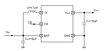
Typical Application Circuit
Quality Reports
Technical Document
Packages
XC9142 Series Part Numbers
| Part number | Sample | Type | Output Voltage | Oscillation Frequency | Packages | EDA | Online Store |
|---|---|---|---|---|---|---|---|
|
|
|
|
|
|
|
|
|
| XC9142A18C0R-G | Fixed Output Voltage,Soft-start,Chip Enable,CL Discharge,Load Disconnection Function | 1.8V | 1.2MHz | WLP-6-01 |
|
||
| XC9142A18CER-G | Fixed Output Voltage,Soft-start,Chip Enable,CL Discharge,Load Disconnection Function | 1.8V | 1.2MHz | USP-6C |
|
||
| XC9142A18CMR-G | Fixed Output Voltage,Soft-start,Chip Enable,CL Discharge,Load Disconnection Function | 1.8V | 1.2MHz | SOT-25 |
|
||
| XC9142A18D0R-G | Fixed Output Voltage,Soft-start,Chip Enable,CL Discharge,Load Disconnection Function | 1.8V | 3.0MHz | WLP-6-01 |
|
||
| XC9142A18DER-G | Fixed Output Voltage,Soft-start,Chip Enable,CL Discharge,Load Disconnection Function | 1.8V | 3.0MHz | USP-6C |
|
||
| XC9142A18DMR-G | Fixed Output Voltage,Soft-start,Chip Enable,CL Discharge,Load Disconnection Function | 1.8V | 3.0MHz | SOT-25 |
|
||
| XC9142A19C0R-G | Fixed Output Voltage,Soft-start,Chip Enable,CL Discharge,Load Disconnection Function | 1.9V | 1.2MHz | WLP-6-01 |
|
||
| XC9142A19CER-G | Fixed Output Voltage,Soft-start,Chip Enable,CL Discharge,Load Disconnection Function | 1.9V | 1.2MHz | USP-6C |
|
||
| XC9142A19CMR-G | Fixed Output Voltage,Soft-start,Chip Enable,CL Discharge,Load Disconnection Function | 1.9V | 1.2MHz | SOT-25 |
|
||
| XC9142A19D0R-G | Fixed Output Voltage,Soft-start,Chip Enable,CL Discharge,Load Disconnection Function | 1.9V | 3.0MHz | WLP-6-01 |
|
||
| XC9142A19DER-G | Fixed Output Voltage,Soft-start,Chip Enable,CL Discharge,Load Disconnection Function | 1.9V | 3.0MHz | USP-6C |
|
||
| XC9142A19DMR-G | Fixed Output Voltage,Soft-start,Chip Enable,CL Discharge,Load Disconnection Function | 1.9V | 3.0MHz | SOT-25 |
|
||
| XC9142A20C0R-G | Fixed Output Voltage,Soft-start,Chip Enable,CL Discharge,Load Disconnection Function | 2.0V | 1.2MHz | WLP-6-01 |
|
||
| XC9142A20CER-G | Fixed Output Voltage,Soft-start,Chip Enable,CL Discharge,Load Disconnection Function | 2.0V | 1.2MHz | USP-6C |
|
||
| XC9142A20CMR-G | Fixed Output Voltage,Soft-start,Chip Enable,CL Discharge,Load Disconnection Function | 2.0V | 1.2MHz | SOT-25 |
|
||
| XC9142A20D0R-G | Fixed Output Voltage,Soft-start,Chip Enable,CL Discharge,Load Disconnection Function | 2.0V | 3.0MHz | WLP-6-01 |
|
||
| XC9142A20DER-G | Fixed Output Voltage,Soft-start,Chip Enable,CL Discharge,Load Disconnection Function | 2.0V | 3.0MHz | USP-6C |
|
||
| XC9142A20DMR-G | Fixed Output Voltage,Soft-start,Chip Enable,CL Discharge,Load Disconnection Function | 2.0V | 3.0MHz | SOT-25 |
|
||
| XC9142A21C0R-G | Fixed Output Voltage,Soft-start,Chip Enable,CL Discharge,Load Disconnection Function | 2.1V | 1.2MHz | WLP-6-01 |
|
||
| XC9142A21CER-G | Fixed Output Voltage,Soft-start,Chip Enable,CL Discharge,Load Disconnection Function | 2.1V | 1.2MHz | USP-6C |
|
||
| XC9142A21CMR-G | Fixed Output Voltage,Soft-start,Chip Enable,CL Discharge,Load Disconnection Function | 2.1V | 1.2MHz | SOT-25 |
|
||
| XC9142A21D0R-G | Fixed Output Voltage,Soft-start,Chip Enable,CL Discharge,Load Disconnection Function | 2.1V | 3.0MHz | WLP-6-01 |
|
||
| XC9142A21DER-G | Fixed Output Voltage,Soft-start,Chip Enable,CL Discharge,Load Disconnection Function | 2.1V | 3.0MHz | USP-6C |
|
||
| XC9142A21DMR-G | Fixed Output Voltage,Soft-start,Chip Enable,CL Discharge,Load Disconnection Function | 2.1V | 3.0MHz | SOT-25 |
|
||
| XC9142A22C0R-G | Fixed Output Voltage,Soft-start,Chip Enable,CL Discharge,Load Disconnection Function | 2.2V | 1.2MHz | WLP-6-01 |
|
||
| XC9142A22CER-G | Fixed Output Voltage,Soft-start,Chip Enable,CL Discharge,Load Disconnection Function | 2.2V | 1.2MHz | USP-6C |
|
||
| XC9142A22CMR-G | Fixed Output Voltage,Soft-start,Chip Enable,CL Discharge,Load Disconnection Function | 2.2V | 1.2MHz | SOT-25 |
|
||
| XC9142A22D0R-G | Fixed Output Voltage,Soft-start,Chip Enable,CL Discharge,Load Disconnection Function | 2.2V | 3.0MHz | WLP-6-01 |
|
||
| XC9142A22DER-G | Fixed Output Voltage,Soft-start,Chip Enable,CL Discharge,Load Disconnection Function | 2.2V | 3.0MHz | USP-6C |
|
||
| XC9142A22DMR-G | Fixed Output Voltage,Soft-start,Chip Enable,CL Discharge,Load Disconnection Function | 2.2V | 3.0MHz | SOT-25 |
|
||
| XC9142A23C0R-G | Fixed Output Voltage,Soft-start,Chip Enable,CL Discharge,Load Disconnection Function | 2.3V | 1.2MHz | WLP-6-01 |
|
||
| XC9142A23CER-G | Fixed Output Voltage,Soft-start,Chip Enable,CL Discharge,Load Disconnection Function | 2.3V | 1.2MHz | USP-6C |
|
||
| XC9142A23CMR-G | Fixed Output Voltage,Soft-start,Chip Enable,CL Discharge,Load Disconnection Function | 2.3V | 1.2MHz | SOT-25 |
|
||
| XC9142A23D0R-G | Fixed Output Voltage,Soft-start,Chip Enable,CL Discharge,Load Disconnection Function | 2.3V | 3.0MHz | WLP-6-01 |
|
||
| XC9142A23DER-G | Fixed Output Voltage,Soft-start,Chip Enable,CL Discharge,Load Disconnection Function | 2.3V | 3.0MHz | USP-6C |
|
||
| XC9142A23DMR-G | Fixed Output Voltage,Soft-start,Chip Enable,CL Discharge,Load Disconnection Function | 2.3V | 3.0MHz | SOT-25 |
|
||
| XC9142A24C0R-G | Fixed Output Voltage,Soft-start,Chip Enable,CL Discharge,Load Disconnection Function | 2.4V | 1.2MHz | WLP-6-01 |
|
||
| XC9142A24CER-G | Fixed Output Voltage,Soft-start,Chip Enable,CL Discharge,Load Disconnection Function | 2.4V | 1.2MHz | USP-6C |
|
||
| XC9142A24CMR-G | Fixed Output Voltage,Soft-start,Chip Enable,CL Discharge,Load Disconnection Function | 2.4V | 1.2MHz | SOT-25 |
|
||
| XC9142A24D0R-G | Fixed Output Voltage,Soft-start,Chip Enable,CL Discharge,Load Disconnection Function | 2.4V | 3.0MHz | WLP-6-01 |
|
||
| XC9142A24DER-G | Fixed Output Voltage,Soft-start,Chip Enable,CL Discharge,Load Disconnection Function | 2.4V | 3.0MHz | USP-6C |
|
||
| XC9142A24DMR-G | Fixed Output Voltage,Soft-start,Chip Enable,CL Discharge,Load Disconnection Function | 2.4V | 3.0MHz | SOT-25 |
|
||
| XC9142A25C0R-G | Fixed Output Voltage,Soft-start,Chip Enable,CL Discharge,Load Disconnection Function | 2.5V | 1.2MHz | WLP-6-01 |
|
||
| XC9142A25CER-G | Fixed Output Voltage,Soft-start,Chip Enable,CL Discharge,Load Disconnection Function | 2.5V | 1.2MHz | USP-6C |
|
||
| XC9142A25CMR-G | Fixed Output Voltage,Soft-start,Chip Enable,CL Discharge,Load Disconnection Function | 2.5V | 1.2MHz | SOT-25 |
|
||
| XC9142A25D0R-G | Fixed Output Voltage,Soft-start,Chip Enable,CL Discharge,Load Disconnection Function | 2.5V | 3.0MHz | WLP-6-01 |
|
||
| XC9142A25DER-G | Fixed Output Voltage,Soft-start,Chip Enable,CL Discharge,Load Disconnection Function | 2.5V | 3.0MHz | USP-6C |
|
||
| XC9142A25DMR-G | Fixed Output Voltage,Soft-start,Chip Enable,CL Discharge,Load Disconnection Function | 2.5V | 3.0MHz | SOT-25 |
|
||
| XC9142A26C0R-G | Fixed Output Voltage,Soft-start,Chip Enable,CL Discharge,Load Disconnection Function | 2.6V | 1.2MHz | WLP-6-01 |
|
||
| XC9142A26CER-G | Fixed Output Voltage,Soft-start,Chip Enable,CL Discharge,Load Disconnection Function | 2.6V | 1.2MHz | USP-6C |
|
||
| XC9142A26CMR-G | Fixed Output Voltage,Soft-start,Chip Enable,CL Discharge,Load Disconnection Function | 2.6V | 1.2MHz | SOT-25 |
|
||
| XC9142A26D0R-G | Fixed Output Voltage,Soft-start,Chip Enable,CL Discharge,Load Disconnection Function | 2.6V | 3.0MHz | WLP-6-01 |
|
||
| XC9142A26DER-G | Fixed Output Voltage,Soft-start,Chip Enable,CL Discharge,Load Disconnection Function | 2.6V | 3.0MHz | USP-6C |
|
||
| XC9142A26DMR-G | Fixed Output Voltage,Soft-start,Chip Enable,CL Discharge,Load Disconnection Function | 2.6V | 3.0MHz | SOT-25 |
|
||
| XC9142A27C0R-G | Fixed Output Voltage,Soft-start,Chip Enable,CL Discharge,Load Disconnection Function | 2.7V | 1.2MHz | WLP-6-01 |
|
||
| XC9142A27CER-G | Fixed Output Voltage,Soft-start,Chip Enable,CL Discharge,Load Disconnection Function | 2.7V | 1.2MHz | USP-6C |
|
||
| XC9142A27CMR-G | Fixed Output Voltage,Soft-start,Chip Enable,CL Discharge,Load Disconnection Function | 2.7V | 1.2MHz | SOT-25 |
|
||
| XC9142A27D0R-G | Fixed Output Voltage,Soft-start,Chip Enable,CL Discharge,Load Disconnection Function | 2.7V | 3.0MHz | WLP-6-01 |
|
||
| XC9142A27DER-G | Fixed Output Voltage,Soft-start,Chip Enable,CL Discharge,Load Disconnection Function | 2.7V | 3.0MHz | USP-6C |
|
||
| XC9142A27DMR-G | Fixed Output Voltage,Soft-start,Chip Enable,CL Discharge,Load Disconnection Function | 2.7V | 3.0MHz | SOT-25 |
|
||
| XC9142A28C0R-G | Fixed Output Voltage,Soft-start,Chip Enable,CL Discharge,Load Disconnection Function | 2.8V | 1.2MHz | WLP-6-01 |
|
||
| XC9142A28CER-G | Fixed Output Voltage,Soft-start,Chip Enable,CL Discharge,Load Disconnection Function | 2.8V | 1.2MHz | USP-6C |
|
||
| XC9142A28CMR-G | Fixed Output Voltage,Soft-start,Chip Enable,CL Discharge,Load Disconnection Function | 2.8V | 1.2MHz | SOT-25 |
|
||
| XC9142A28D0R-G | Fixed Output Voltage,Soft-start,Chip Enable,CL Discharge,Load Disconnection Function | 2.8V | 3.0MHz | WLP-6-01 |
|
||
| XC9142A28DER-G | Fixed Output Voltage,Soft-start,Chip Enable,CL Discharge,Load Disconnection Function | 2.8V | 3.0MHz | USP-6C |
|
||
| XC9142A28DMR-G | Fixed Output Voltage,Soft-start,Chip Enable,CL Discharge,Load Disconnection Function | 2.8V | 3.0MHz | SOT-25 |
|
||
| XC9142A29C0R-G | Fixed Output Voltage,Soft-start,Chip Enable,CL Discharge,Load Disconnection Function | 2.9V | 1.2MHz | WLP-6-01 |
|
||
| XC9142A29CER-G | Fixed Output Voltage,Soft-start,Chip Enable,CL Discharge,Load Disconnection Function | 2.9V | 1.2MHz | USP-6C |
|
||
| XC9142A29CMR-G | Fixed Output Voltage,Soft-start,Chip Enable,CL Discharge,Load Disconnection Function | 2.9V | 1.2MHz | SOT-25 |
|
||
| XC9142A29D0R-G | Fixed Output Voltage,Soft-start,Chip Enable,CL Discharge,Load Disconnection Function | 2.9V | 3.0MHz | WLP-6-01 |
|
||
| XC9142A29DER-G | Fixed Output Voltage,Soft-start,Chip Enable,CL Discharge,Load Disconnection Function | 2.9V | 3.0MHz | USP-6C |
|
||
| XC9142A29DMR-G | Fixed Output Voltage,Soft-start,Chip Enable,CL Discharge,Load Disconnection Function | 2.9V | 3.0MHz | SOT-25 |
|
||
| XC9142A30C0R-G | Fixed Output Voltage,Soft-start,Chip Enable,CL Discharge,Load Disconnection Function | 3.0V | 1.2MHz | WLP-6-01 |
|
||
| XC9142A30CER-G | Fixed Output Voltage,Soft-start,Chip Enable,CL Discharge,Load Disconnection Function | 3.0V | 1.2MHz | USP-6C |
|
||
| XC9142A30CMR-G | Fixed Output Voltage,Soft-start,Chip Enable,CL Discharge,Load Disconnection Function | 3.0V | 1.2MHz | SOT-25 |
|
||
| XC9142A30D0R-G | Fixed Output Voltage,Soft-start,Chip Enable,CL Discharge,Load Disconnection Function | 3.0V | 3.0MHz | WLP-6-01 |
|
||
| XC9142A30DER-G | Fixed Output Voltage,Soft-start,Chip Enable,CL Discharge,Load Disconnection Function | 3.0V | 3.0MHz | USP-6C |
|
||
| XC9142A30DMR-G | Fixed Output Voltage,Soft-start,Chip Enable,CL Discharge,Load Disconnection Function | 3.0V | 3.0MHz | SOT-25 |
|
||
| XC9142A31C0R-G | Fixed Output Voltage,Soft-start,Chip Enable,CL Discharge,Load Disconnection Function | 3.1V | 1.2MHz | WLP-6-01 |
|
||
| XC9142A31CER-G | Fixed Output Voltage,Soft-start,Chip Enable,CL Discharge,Load Disconnection Function | 3.1V | 1.2MHz | USP-6C |
|
||
| XC9142A31CMR-G | Fixed Output Voltage,Soft-start,Chip Enable,CL Discharge,Load Disconnection Function | 3.1V | 1.2MHz | SOT-25 |
|
||
| XC9142A31D0R-G | Fixed Output Voltage,Soft-start,Chip Enable,CL Discharge,Load Disconnection Function | 3.1V | 3.0MHz | WLP-6-01 |
|
||
| XC9142A31DER-G | Fixed Output Voltage,Soft-start,Chip Enable,CL Discharge,Load Disconnection Function | 3.1V | 3.0MHz | USP-6C |
|
||
| XC9142A31DMR-G | Fixed Output Voltage,Soft-start,Chip Enable,CL Discharge,Load Disconnection Function | 3.1V | 3.0MHz | SOT-25 |
|
||
| XC9142A32C0R-G | Fixed Output Voltage,Soft-start,Chip Enable,CL Discharge,Load Disconnection Function | 3.2V | 1.2MHz | WLP-6-01 |
|
||
| XC9142A32CER-G | Fixed Output Voltage,Soft-start,Chip Enable,CL Discharge,Load Disconnection Function | 3.2V | 1.2MHz | USP-6C |
|
||
| XC9142A32CMR-G | Fixed Output Voltage,Soft-start,Chip Enable,CL Discharge,Load Disconnection Function | 3.2V | 1.2MHz | SOT-25 |
|
||
| XC9142A32D0R-G | Fixed Output Voltage,Soft-start,Chip Enable,CL Discharge,Load Disconnection Function | 3.2V | 3.0MHz | WLP-6-01 |
|
||
| XC9142A32DER-G | Fixed Output Voltage,Soft-start,Chip Enable,CL Discharge,Load Disconnection Function | 3.2V | 3.0MHz | USP-6C |
|
||
| XC9142A32DMR-G | Fixed Output Voltage,Soft-start,Chip Enable,CL Discharge,Load Disconnection Function | 3.2V | 3.0MHz | SOT-25 |
|
||
| XC9142A33C0R-G | Fixed Output Voltage,Soft-start,Chip Enable,CL Discharge,Load Disconnection Function | 3.3V | 1.2MHz | WLP-6-01 |
|
||
| XC9142A33CER-G | Fixed Output Voltage,Soft-start,Chip Enable,CL Discharge,Load Disconnection Function | 3.3V | 1.2MHz | USP-6C |
|
||
| XC9142A33CMR-G | Fixed Output Voltage,Soft-start,Chip Enable,CL Discharge,Load Disconnection Function | 3.3V | 1.2MHz | SOT-25 |
|
||
| XC9142A33D0R-G | Fixed Output Voltage,Soft-start,Chip Enable,CL Discharge,Load Disconnection Function | 3.3V | 3.0MHz | WLP-6-01 |
|
||
| XC9142A33DER-G | Fixed Output Voltage,Soft-start,Chip Enable,CL Discharge,Load Disconnection Function | 3.3V | 3.0MHz | USP-6C |
|
||
| XC9142A33DMR-G | Fixed Output Voltage,Soft-start,Chip Enable,CL Discharge,Load Disconnection Function | 3.3V | 3.0MHz | SOT-25 |
|
||
| XC9142A34C0R-G | Fixed Output Voltage,Soft-start,Chip Enable,CL Discharge,Load Disconnection Function | 3.4V | 1.2MHz | WLP-6-01 |
|
||
| XC9142A34CER-G | Fixed Output Voltage,Soft-start,Chip Enable,CL Discharge,Load Disconnection Function | 3.4V | 1.2MHz | USP-6C |
|
||
| XC9142A34CMR-G | Fixed Output Voltage,Soft-start,Chip Enable,CL Discharge,Load Disconnection Function | 3.4V | 1.2MHz | SOT-25 |
|
||
| XC9142A34D0R-G | Fixed Output Voltage,Soft-start,Chip Enable,CL Discharge,Load Disconnection Function | 3.4V | 3.0MHz | WLP-6-01 |
|
||
| XC9142A34DER-G | Fixed Output Voltage,Soft-start,Chip Enable,CL Discharge,Load Disconnection Function | 3.4V | 3.0MHz | USP-6C |
|
||
| XC9142A34DMR-G | Fixed Output Voltage,Soft-start,Chip Enable,CL Discharge,Load Disconnection Function | 3.4V | 3.0MHz | SOT-25 |
|
||
| XC9142A35C0R-G | Fixed Output Voltage,Soft-start,Chip Enable,CL Discharge,Load Disconnection Function | 3.5V | 1.2MHz | WLP-6-01 |
|
||
| XC9142A35CER-G | Fixed Output Voltage,Soft-start,Chip Enable,CL Discharge,Load Disconnection Function | 3.5V | 1.2MHz | USP-6C |
|
||
| XC9142A35CMR-G | Fixed Output Voltage,Soft-start,Chip Enable,CL Discharge,Load Disconnection Function | 3.5V | 1.2MHz | SOT-25 |
|
||
| XC9142A35D0R-G | Fixed Output Voltage,Soft-start,Chip Enable,CL Discharge,Load Disconnection Function | 3.5V | 3.0MHz | WLP-6-01 |
|
||
| XC9142A35DER-G | Fixed Output Voltage,Soft-start,Chip Enable,CL Discharge,Load Disconnection Function | 3.5V | 3.0MHz | USP-6C |
|
||
| XC9142A35DMR-G | Fixed Output Voltage,Soft-start,Chip Enable,CL Discharge,Load Disconnection Function | 3.5V | 3.0MHz | SOT-25 |
|
||
| XC9142A36C0R-G | Fixed Output Voltage,Soft-start,Chip Enable,CL Discharge,Load Disconnection Function | 3.6V | 1.2MHz | WLP-6-01 |
|
||
| XC9142A36CER-G | Fixed Output Voltage,Soft-start,Chip Enable,CL Discharge,Load Disconnection Function | 3.6V | 1.2MHz | USP-6C |
|
||
| XC9142A36CMR-G | Fixed Output Voltage,Soft-start,Chip Enable,CL Discharge,Load Disconnection Function | 3.6V | 1.2MHz | SOT-25 |
|
||
| XC9142A36D0R-G | Fixed Output Voltage,Soft-start,Chip Enable,CL Discharge,Load Disconnection Function | 3.6V | 3.0MHz | WLP-6-01 |
|
||
| XC9142A36DER-G | Fixed Output Voltage,Soft-start,Chip Enable,CL Discharge,Load Disconnection Function | 3.6V | 3.0MHz | USP-6C |
|
||
| XC9142A36DMR-G | Fixed Output Voltage,Soft-start,Chip Enable,CL Discharge,Load Disconnection Function | 3.6V | 3.0MHz | SOT-25 |
|
||
| XC9142A37C0R-G | Fixed Output Voltage,Soft-start,Chip Enable,CL Discharge,Load Disconnection Function | 3.7V | 1.2MHz | WLP-6-01 |
|
||
| XC9142A37CER-G | Fixed Output Voltage,Soft-start,Chip Enable,CL Discharge,Load Disconnection Function | 3.7V | 1.2MHz | USP-6C |
|
||
| XC9142A37CMR-G | Fixed Output Voltage,Soft-start,Chip Enable,CL Discharge,Load Disconnection Function | 3.7V | 1.2MHz | SOT-25 |
|
||
| XC9142A37D0R-G | Fixed Output Voltage,Soft-start,Chip Enable,CL Discharge,Load Disconnection Function | 3.7V | 3.0MHz | WLP-6-01 |
|
||
| XC9142A37DER-G | Fixed Output Voltage,Soft-start,Chip Enable,CL Discharge,Load Disconnection Function | 3.7V | 3.0MHz | USP-6C |
|
||
| XC9142A37DMR-G | Fixed Output Voltage,Soft-start,Chip Enable,CL Discharge,Load Disconnection Function | 3.7V | 3.0MHz | SOT-25 |
|
||
| XC9142A38C0R-G | Fixed Output Voltage,Soft-start,Chip Enable,CL Discharge,Load Disconnection Function | 3.8V | 1.2MHz | WLP-6-01 |
|
||
| XC9142A38CER-G | Fixed Output Voltage,Soft-start,Chip Enable,CL Discharge,Load Disconnection Function | 3.8V | 1.2MHz | USP-6C |
|
||
| XC9142A38CMR-G | Fixed Output Voltage,Soft-start,Chip Enable,CL Discharge,Load Disconnection Function | 3.8V | 1.2MHz | SOT-25 |
|
||
| XC9142A38D0R-G | Fixed Output Voltage,Soft-start,Chip Enable,CL Discharge,Load Disconnection Function | 3.8V | 3.0MHz | WLP-6-01 |
|
||
| XC9142A38DER-G | Fixed Output Voltage,Soft-start,Chip Enable,CL Discharge,Load Disconnection Function | 3.8V | 3.0MHz | USP-6C |
|
||
| XC9142A38DMR-G | Fixed Output Voltage,Soft-start,Chip Enable,CL Discharge,Load Disconnection Function | 3.8V | 3.0MHz | SOT-25 |
|
||
| XC9142A39C0R-G | Fixed Output Voltage,Soft-start,Chip Enable,CL Discharge,Load Disconnection Function | 3.9V | 1.2MHz | WLP-6-01 |
|
||
| XC9142A39CER-G | Fixed Output Voltage,Soft-start,Chip Enable,CL Discharge,Load Disconnection Function | 3.9V | 1.2MHz | USP-6C |
|
||
| XC9142A39CMR-G | Fixed Output Voltage,Soft-start,Chip Enable,CL Discharge,Load Disconnection Function | 3.9V | 1.2MHz | SOT-25 |
|
||
| XC9142A39D0R-G | Fixed Output Voltage,Soft-start,Chip Enable,CL Discharge,Load Disconnection Function | 3.9V | 3.0MHz | WLP-6-01 |
|
||
| XC9142A39DER-G | Fixed Output Voltage,Soft-start,Chip Enable,CL Discharge,Load Disconnection Function | 3.9V | 3.0MHz | USP-6C |
|
||
| XC9142A39DMR-G | Fixed Output Voltage,Soft-start,Chip Enable,CL Discharge,Load Disconnection Function | 3.9V | 3.0MHz | SOT-25 |
|
||
| XC9142A40C0R-G | Fixed Output Voltage,Soft-start,Chip Enable,CL Discharge,Load Disconnection Function | 4.0V | 1.2MHz | WLP-6-01 |
|
||
| XC9142A40CER-G | Fixed Output Voltage,Soft-start,Chip Enable,CL Discharge,Load Disconnection Function | 4.0V | 1.2MHz | USP-6C |
|
||
| XC9142A40CMR-G | Fixed Output Voltage,Soft-start,Chip Enable,CL Discharge,Load Disconnection Function | 4.0V | 1.2MHz | SOT-25 |
|
||
| XC9142A40D0R-G | Fixed Output Voltage,Soft-start,Chip Enable,CL Discharge,Load Disconnection Function | 4.0V | 3.0MHz | WLP-6-01 |
|
||
| XC9142A40DER-G | Fixed Output Voltage,Soft-start,Chip Enable,CL Discharge,Load Disconnection Function | 4.0V | 3.0MHz | USP-6C |
|
||
| XC9142A40DMR-G | Fixed Output Voltage,Soft-start,Chip Enable,CL Discharge,Load Disconnection Function | 4.0V | 3.0MHz | SOT-25 |
|
||
| XC9142A41C0R-G | Fixed Output Voltage,Soft-start,Chip Enable,CL Discharge,Load Disconnection Function | 4.1V | 1.2MHz | WLP-6-01 |
|
||
| XC9142A41CER-G | Fixed Output Voltage,Soft-start,Chip Enable,CL Discharge,Load Disconnection Function | 4.1V | 1.2MHz | USP-6C |
|
||
| XC9142A41CMR-G | Fixed Output Voltage,Soft-start,Chip Enable,CL Discharge,Load Disconnection Function | 4.1V | 1.2MHz | SOT-25 |
|
||
| XC9142A41D0R-G | Fixed Output Voltage,Soft-start,Chip Enable,CL Discharge,Load Disconnection Function | 4.1V | 3.0MHz | WLP-6-01 |
|
||
| XC9142A41DER-G | Fixed Output Voltage,Soft-start,Chip Enable,CL Discharge,Load Disconnection Function | 4.1V | 3.0MHz | USP-6C |
|
||
| XC9142A41DMR-G | Fixed Output Voltage,Soft-start,Chip Enable,CL Discharge,Load Disconnection Function | 4.1V | 3.0MHz | SOT-25 |
|
||
| XC9142A42C0R-G | Fixed Output Voltage,Soft-start,Chip Enable,CL Discharge,Load Disconnection Function | 4.2V | 1.2MHz | WLP-6-01 |
|
||
| XC9142A42CER-G | Fixed Output Voltage,Soft-start,Chip Enable,CL Discharge,Load Disconnection Function | 4.2V | 1.2MHz | USP-6C |
|
||
| XC9142A42CMR-G | Fixed Output Voltage,Soft-start,Chip Enable,CL Discharge,Load Disconnection Function | 4.2V | 1.2MHz | SOT-25 |
|
||
| XC9142A42D0R-G | Fixed Output Voltage,Soft-start,Chip Enable,CL Discharge,Load Disconnection Function | 4.2V | 3.0MHz | WLP-6-01 |
|
||
| XC9142A42DER-G | Fixed Output Voltage,Soft-start,Chip Enable,CL Discharge,Load Disconnection Function | 4.2V | 3.0MHz | USP-6C |
|
||
| XC9142A42DMR-G | Fixed Output Voltage,Soft-start,Chip Enable,CL Discharge,Load Disconnection Function | 4.2V | 3.0MHz | SOT-25 |
|
||
| XC9142A43C0R-G | Fixed Output Voltage,Soft-start,Chip Enable,CL Discharge,Load Disconnection Function | 4.3V | 1.2MHz | WLP-6-01 |
|
||
| XC9142A43CER-G | Fixed Output Voltage,Soft-start,Chip Enable,CL Discharge,Load Disconnection Function | 4.3V | 1.2MHz | USP-6C |
|
||
| XC9142A43CMR-G | Fixed Output Voltage,Soft-start,Chip Enable,CL Discharge,Load Disconnection Function | 4.3V | 1.2MHz | SOT-25 |
|
||
| XC9142A43D0R-G | Fixed Output Voltage,Soft-start,Chip Enable,CL Discharge,Load Disconnection Function | 4.3V | 3.0MHz | WLP-6-01 |
|
||
| XC9142A43DER-G | Fixed Output Voltage,Soft-start,Chip Enable,CL Discharge,Load Disconnection Function | 4.3V | 3.0MHz | USP-6C |
|
||
| XC9142A43DMR-G | Fixed Output Voltage,Soft-start,Chip Enable,CL Discharge,Load Disconnection Function | 4.3V | 3.0MHz | SOT-25 |
|
||
| XC9142A44C0R-G | Fixed Output Voltage,Soft-start,Chip Enable,CL Discharge,Load Disconnection Function | 4.4V | 1.2MHz | WLP-6-01 |
|
||
| XC9142A44CER-G | Fixed Output Voltage,Soft-start,Chip Enable,CL Discharge,Load Disconnection Function | 4.4V | 1.2MHz | USP-6C |
|
||
| XC9142A44CMR-G | Fixed Output Voltage,Soft-start,Chip Enable,CL Discharge,Load Disconnection Function | 4.4V | 1.2MHz | SOT-25 |
|
||
| XC9142A44D0R-G | Fixed Output Voltage,Soft-start,Chip Enable,CL Discharge,Load Disconnection Function | 4.4V | 3.0MHz | WLP-6-01 |
|
||
| XC9142A44DER-G | Fixed Output Voltage,Soft-start,Chip Enable,CL Discharge,Load Disconnection Function | 4.4V | 3.0MHz | USP-6C |
|
||
| XC9142A44DMR-G | Fixed Output Voltage,Soft-start,Chip Enable,CL Discharge,Load Disconnection Function | 4.4V | 3.0MHz | SOT-25 |
|
||
| XC9142A45C0R-G | Fixed Output Voltage,Soft-start,Chip Enable,CL Discharge,Load Disconnection Function | 4.5V | 1.2MHz | WLP-6-01 |
|
||
| XC9142A45CER-G | Fixed Output Voltage,Soft-start,Chip Enable,CL Discharge,Load Disconnection Function | 4.5V | 1.2MHz | USP-6C |
|
||
| XC9142A45CMR-G | Fixed Output Voltage,Soft-start,Chip Enable,CL Discharge,Load Disconnection Function | 4.5V | 1.2MHz | SOT-25 |
|
||
| XC9142A45D0R-G | Fixed Output Voltage,Soft-start,Chip Enable,CL Discharge,Load Disconnection Function | 4.5V | 3.0MHz | WLP-6-01 |
|
||
| XC9142A45DER-G | Fixed Output Voltage,Soft-start,Chip Enable,CL Discharge,Load Disconnection Function | 4.5V | 3.0MHz | USP-6C |
|
||
| XC9142A45DMR-G | Fixed Output Voltage,Soft-start,Chip Enable,CL Discharge,Load Disconnection Function | 4.5V | 3.0MHz | SOT-25 |
|
||
| XC9142A46C0R-G | Fixed Output Voltage,Soft-start,Chip Enable,CL Discharge,Load Disconnection Function | 4.6V | 1.2MHz | WLP-6-01 |
|
||
| XC9142A46CER-G | Fixed Output Voltage,Soft-start,Chip Enable,CL Discharge,Load Disconnection Function | 4.6V | 1.2MHz | USP-6C |
|
||
| XC9142A46CMR-G | Fixed Output Voltage,Soft-start,Chip Enable,CL Discharge,Load Disconnection Function | 4.6V | 1.2MHz | SOT-25 |
|
||
| XC9142A46D0R-G | Fixed Output Voltage,Soft-start,Chip Enable,CL Discharge,Load Disconnection Function | 4.6V | 3.0MHz | WLP-6-01 |
|
||
| XC9142A46DER-G | Fixed Output Voltage,Soft-start,Chip Enable,CL Discharge,Load Disconnection Function | 4.6V | 3.0MHz | USP-6C |
|
||
| XC9142A46DMR-G | Fixed Output Voltage,Soft-start,Chip Enable,CL Discharge,Load Disconnection Function | 4.6V | 3.0MHz | SOT-25 |
|
||
| XC9142A47C0R-G | Fixed Output Voltage,Soft-start,Chip Enable,CL Discharge,Load Disconnection Function | 4.7V | 1.2MHz | WLP-6-01 |
|
||
| XC9142A47CER-G | Fixed Output Voltage,Soft-start,Chip Enable,CL Discharge,Load Disconnection Function | 4.7V | 1.2MHz | USP-6C |
|
||
| XC9142A47CMR-G | Fixed Output Voltage,Soft-start,Chip Enable,CL Discharge,Load Disconnection Function | 4.7V | 1.2MHz | SOT-25 |
|
||
| XC9142A47D0R-G | Fixed Output Voltage,Soft-start,Chip Enable,CL Discharge,Load Disconnection Function | 4.7V | 3.0MHz | WLP-6-01 |
|
||
| XC9142A47DER-G | Fixed Output Voltage,Soft-start,Chip Enable,CL Discharge,Load Disconnection Function | 4.7V | 3.0MHz | USP-6C |
|
||
| XC9142A47DMR-G | Fixed Output Voltage,Soft-start,Chip Enable,CL Discharge,Load Disconnection Function | 4.7V | 3.0MHz | SOT-25 |
|
||
| XC9142A48C0R-G | Fixed Output Voltage,Soft-start,Chip Enable,CL Discharge,Load Disconnection Function | 4.8V | 1.2MHz | WLP-6-01 |
|
||
| XC9142A48CER-G | Fixed Output Voltage,Soft-start,Chip Enable,CL Discharge,Load Disconnection Function | 4.8V | 1.2MHz | USP-6C |
|
||
| XC9142A48CMR-G | Fixed Output Voltage,Soft-start,Chip Enable,CL Discharge,Load Disconnection Function | 4.8V | 1.2MHz | SOT-25 |
|
||
| XC9142A48D0R-G | Fixed Output Voltage,Soft-start,Chip Enable,CL Discharge,Load Disconnection Function | 4.8V | 3.0MHz | WLP-6-01 |
|
||
| XC9142A48DER-G | Fixed Output Voltage,Soft-start,Chip Enable,CL Discharge,Load Disconnection Function | 4.8V | 3.0MHz | USP-6C |
|
||
| XC9142A48DMR-G | Fixed Output Voltage,Soft-start,Chip Enable,CL Discharge,Load Disconnection Function | 4.8V | 3.0MHz | SOT-25 |
|
||
| XC9142A49C0R-G | Fixed Output Voltage,Soft-start,Chip Enable,CL Discharge,Load Disconnection Function | 4.9V | 1.2MHz | WLP-6-01 |
|
||
| XC9142A49CER-G | Fixed Output Voltage,Soft-start,Chip Enable,CL Discharge,Load Disconnection Function | 4.9V | 1.2MHz | USP-6C |
|
||
| XC9142A49CMR-G | Fixed Output Voltage,Soft-start,Chip Enable,CL Discharge,Load Disconnection Function | 4.9V | 1.2MHz | SOT-25 |
|
||
| XC9142A49D0R-G | Fixed Output Voltage,Soft-start,Chip Enable,CL Discharge,Load Disconnection Function | 4.9V | 3.0MHz | WLP-6-01 |
|
||
| XC9142A49DER-G | Fixed Output Voltage,Soft-start,Chip Enable,CL Discharge,Load Disconnection Function | 4.9V | 3.0MHz | USP-6C |
|
||
| XC9142A49DMR-G | Fixed Output Voltage,Soft-start,Chip Enable,CL Discharge,Load Disconnection Function | 4.9V | 3.0MHz | SOT-25 |
|
||
| XC9142A50C0R-G | Fixed Output Voltage,Soft-start,Chip Enable,CL Discharge,Load Disconnection Function | 5.0V | 1.2MHz | WLP-6-01 |
|
||
| XC9142A50CER-G | Fixed Output Voltage,Soft-start,Chip Enable,CL Discharge,Load Disconnection Function | 5.0V | 1.2MHz | USP-6C |
|
||
| XC9142A50CMR-G | Fixed Output Voltage,Soft-start,Chip Enable,CL Discharge,Load Disconnection Function | 5.0V | 1.2MHz | SOT-25 |
|
||
| XC9142A50D0R-G | Fixed Output Voltage,Soft-start,Chip Enable,CL Discharge,Load Disconnection Function | 5.0V | 3.0MHz | WLP-6-01 |
|
||
| XC9142A50DER-G | Fixed Output Voltage,Soft-start,Chip Enable,CL Discharge,Load Disconnection Function | 5.0V | 3.0MHz | USP-6C |
|
||
| XC9142A50DMR-G | Fixed Output Voltage,Soft-start,Chip Enable,CL Discharge,Load Disconnection Function | 5.0V | 3.0MHz | SOT-25 |
|
||
| XC9142A51C0R-G | Fixed Output Voltage,Soft-start,Chip Enable,CL Discharge,Load Disconnection Function | 5.1V | 1.2MHz | WLP-6-01 |
|
||
| XC9142A51CER-G | Fixed Output Voltage,Soft-start,Chip Enable,CL Discharge,Load Disconnection Function | 5.1V | 1.2MHz | USP-6C |
|
||
| XC9142A51CMR-G | Fixed Output Voltage,Soft-start,Chip Enable,CL Discharge,Load Disconnection Function | 5.1V | 1.2MHz | SOT-25 |
|
||
| XC9142A51D0R-G | Fixed Output Voltage,Soft-start,Chip Enable,CL Discharge,Load Disconnection Function | 5.1V | 3.0MHz | WLP-6-01 |
|
||
| XC9142A51DER-G | Fixed Output Voltage,Soft-start,Chip Enable,CL Discharge,Load Disconnection Function | 5.1V | 3.0MHz | USP-6C |
|
||
| XC9142A51DMR-G | Fixed Output Voltage,Soft-start,Chip Enable,CL Discharge,Load Disconnection Function | 5.1V | 3.0MHz | SOT-25 |
|
||
| XC9142A52C0R-G | Fixed Output Voltage,Soft-start,Chip Enable,CL Discharge,Load Disconnection Function | 5.2V | 1.2MHz | WLP-6-01 |
|
||
| XC9142A52CER-G | Fixed Output Voltage,Soft-start,Chip Enable,CL Discharge,Load Disconnection Function | 5.2V | 1.2MHz | USP-6C |
|
||
| XC9142A52CMR-G | Fixed Output Voltage,Soft-start,Chip Enable,CL Discharge,Load Disconnection Function | 5.2V | 1.2MHz | SOT-25 |
|
||
| XC9142A52D0R-G | Fixed Output Voltage,Soft-start,Chip Enable,CL Discharge,Load Disconnection Function | 5.2V | 3.0MHz | WLP-6-01 |
|
||
| XC9142A52DER-G | Fixed Output Voltage,Soft-start,Chip Enable,CL Discharge,Load Disconnection Function | 5.2V | 3.0MHz | USP-6C |
|
||
| XC9142A52DMR-G | Fixed Output Voltage,Soft-start,Chip Enable,CL Discharge,Load Disconnection Function | 5.2V | 3.0MHz | SOT-25 |
|
||
| XC9142A53C0R-G | Fixed Output Voltage,Soft-start,Chip Enable,CL Discharge,Load Disconnection Function | 5.3V | 1.2MHz | WLP-6-01 |
|
||
| XC9142A53CER-G | Fixed Output Voltage,Soft-start,Chip Enable,CL Discharge,Load Disconnection Function | 5.3V | 1.2MHz | USP-6C |
|
||
| XC9142A53CMR-G | Fixed Output Voltage,Soft-start,Chip Enable,CL Discharge,Load Disconnection Function | 5.3V | 1.2MHz | SOT-25 |
|
||
| XC9142A53D0R-G | Fixed Output Voltage,Soft-start,Chip Enable,CL Discharge,Load Disconnection Function | 5.3V | 3.0MHz | WLP-6-01 |
|
||
| XC9142A53DER-G | Fixed Output Voltage,Soft-start,Chip Enable,CL Discharge,Load Disconnection Function | 5.3V | 3.0MHz | USP-6C |
|
||
| XC9142A53DMR-G | Fixed Output Voltage,Soft-start,Chip Enable,CL Discharge,Load Disconnection Function | 5.3V | 3.0MHz | SOT-25 |
|
||
| XC9142A54C0R-G | Fixed Output Voltage,Soft-start,Chip Enable,CL Discharge,Load Disconnection Function | 5.4V | 1.2MHz | WLP-6-01 |
|
||
| XC9142A54CER-G | Fixed Output Voltage,Soft-start,Chip Enable,CL Discharge,Load Disconnection Function | 5.4V | 1.2MHz | USP-6C |
|
||
| XC9142A54CMR-G | Fixed Output Voltage,Soft-start,Chip Enable,CL Discharge,Load Disconnection Function | 5.4V | 1.2MHz | SOT-25 |
|
||
| XC9142A54D0R-G | Fixed Output Voltage,Soft-start,Chip Enable,CL Discharge,Load Disconnection Function | 5.4V | 3.0MHz | WLP-6-01 |
|
||
| XC9142A54DER-G | Fixed Output Voltage,Soft-start,Chip Enable,CL Discharge,Load Disconnection Function | 5.4V | 3.0MHz | USP-6C |
|
||
| XC9142A54DMR-G | Fixed Output Voltage,Soft-start,Chip Enable,CL Discharge,Load Disconnection Function | 5.4V | 3.0MHz | SOT-25 |
|
||
| XC9142A55C0R-G | Fixed Output Voltage,Soft-start,Chip Enable,CL Discharge,Load Disconnection Function | 5.5V | 1.2MHz | WLP-6-01 |
|
||
| XC9142A55CER-G | Fixed Output Voltage,Soft-start,Chip Enable,CL Discharge,Load Disconnection Function | 5.5V | 1.2MHz | USP-6C |
|
||
| XC9142A55CMR-G | Fixed Output Voltage,Soft-start,Chip Enable,CL Discharge,Load Disconnection Function | 5.5V | 1.2MHz | SOT-25 |
|
||
| XC9142A55D0R-G | Fixed Output Voltage,Soft-start,Chip Enable,CL Discharge,Load Disconnection Function | 5.5V | 3.0MHz | WLP-6-01 |
|
||
| XC9142A55DER-G | Fixed Output Voltage,Soft-start,Chip Enable,CL Discharge,Load Disconnection Function | 5.5V | 3.0MHz | USP-6C |
|
||
| XC9142A55DMR-G | Fixed Output Voltage,Soft-start,Chip Enable,CL Discharge,Load Disconnection Function | 5.5V | 3.0MHz | SOT-25 |
|
||
| XC9142B18C0R-G | Fixed Output Voltage,Soft-start,Chip Enable | 1.8V | 1.2MHz | WLP-6-01 |
|
||
| XC9142B18CER-G | Fixed Output Voltage,Soft-start,Chip Enable | 1.8V | 1.2MHz | USP-6C |
|
||
| XC9142B18CMR-G | Fixed Output Voltage,Soft-start,Chip Enable | 1.8V | 1.2MHz | SOT-25 |
|
||
| XC9142B18D0R-G | Fixed Output Voltage,Soft-start,Chip Enable | 1.8V | 3.0MHz | WLP-6-01 |
|
||
| XC9142B18DER-G | Fixed Output Voltage,Soft-start,Chip Enable | 1.8V | 3.0MHz | USP-6C |
|
||
| XC9142B18DMR-G | Fixed Output Voltage,Soft-start,Chip Enable | 1.8V | 3.0MHz | SOT-25 |
|
||
| XC9142B19C0R-G | Fixed Output Voltage,Soft-start,Chip Enable | 1.9V | 1.2MHz | WLP-6-01 |
|
||
| XC9142B19CER-G | Fixed Output Voltage,Soft-start,Chip Enable | 1.9V | 1.2MHz | USP-6C |
|
||
| XC9142B19CMR-G | Fixed Output Voltage,Soft-start,Chip Enable | 1.9V | 1.2MHz | SOT-25 |
|
||
| XC9142B19D0R-G | Fixed Output Voltage,Soft-start,Chip Enable | 1.9V | 3.0MHz | WLP-6-01 |
|
||
| XC9142B19DER-G | Fixed Output Voltage,Soft-start,Chip Enable | 1.9V | 3.0MHz | USP-6C |
|
||
| XC9142B19DMR-G | Fixed Output Voltage,Soft-start,Chip Enable | 1.9V | 3.0MHz | SOT-25 |
|
||
| XC9142B20C0R-G | Fixed Output Voltage,Soft-start,Chip Enable | 2.0V | 1.2MHz | WLP-6-01 |
|
||
| XC9142B20CER-G | Fixed Output Voltage,Soft-start,Chip Enable | 2.0V | 1.2MHz | USP-6C |
|
||
| XC9142B20CMR-G | Fixed Output Voltage,Soft-start,Chip Enable | 2.0V | 1.2MHz | SOT-25 |
|
||
| XC9142B20D0R-G | Fixed Output Voltage,Soft-start,Chip Enable | 2.0V | 3.0MHz | WLP-6-01 |
|
||
| XC9142B20DER-G | Fixed Output Voltage,Soft-start,Chip Enable | 2.0V | 3.0MHz | USP-6C |
|
||
| XC9142B20DMR-G | Fixed Output Voltage,Soft-start,Chip Enable | 2.0V | 3.0MHz | SOT-25 |
|
||
| XC9142B21C0R-G | Fixed Output Voltage,Soft-start,Chip Enable | 2.1V | 1.2MHz | WLP-6-01 |
|
||
| XC9142B21CER-G | Fixed Output Voltage,Soft-start,Chip Enable | 2.1V | 1.2MHz | USP-6C |
|
||
| XC9142B21CMR-G | Fixed Output Voltage,Soft-start,Chip Enable | 2.1V | 1.2MHz | SOT-25 |
|
||
| XC9142B21D0R-G | Fixed Output Voltage,Soft-start,Chip Enable | 2.1V | 3.0MHz | WLP-6-01 |
|
||
| XC9142B21DER-G | Fixed Output Voltage,Soft-start,Chip Enable | 2.1V | 3.0MHz | USP-6C |
|
||
| XC9142B21DMR-G | Fixed Output Voltage,Soft-start,Chip Enable | 2.1V | 3.0MHz | SOT-25 |
|
||
| XC9142B22C0R-G | Fixed Output Voltage,Soft-start,Chip Enable | 2.2V | 1.2MHz | WLP-6-01 |
|
||
| XC9142B22CER-G | Fixed Output Voltage,Soft-start,Chip Enable | 2.2V | 1.2MHz | USP-6C |
|
||
| XC9142B22CMR-G | Fixed Output Voltage,Soft-start,Chip Enable | 2.2V | 1.2MHz | SOT-25 |
|
||
| XC9142B22D0R-G | Fixed Output Voltage,Soft-start,Chip Enable | 2.2V | 3.0MHz | WLP-6-01 |
|
||
| XC9142B22DER-G | Fixed Output Voltage,Soft-start,Chip Enable | 2.2V | 3.0MHz | USP-6C |
|
||
| XC9142B22DMR-G | Fixed Output Voltage,Soft-start,Chip Enable | 2.2V | 3.0MHz | SOT-25 |
|
||
| XC9142B23C0R-G | Fixed Output Voltage,Soft-start,Chip Enable | 2.3V | 1.2MHz | WLP-6-01 |
|
||
| XC9142B23CER-G | Fixed Output Voltage,Soft-start,Chip Enable | 2.3V | 1.2MHz | USP-6C |
|
||
| XC9142B23CMR-G | Fixed Output Voltage,Soft-start,Chip Enable | 2.3V | 1.2MHz | SOT-25 |
|
||
| XC9142B23D0R-G | Fixed Output Voltage,Soft-start,Chip Enable | 2.3V | 3.0MHz | WLP-6-01 |
|
||
| XC9142B23DER-G | Fixed Output Voltage,Soft-start,Chip Enable | 2.3V | 3.0MHz | USP-6C |
|
||
| XC9142B23DMR-G | Fixed Output Voltage,Soft-start,Chip Enable | 2.3V | 3.0MHz | SOT-25 |
|
||
| XC9142B24C0R-G | Fixed Output Voltage,Soft-start,Chip Enable | 2.4V | 1.2MHz | WLP-6-01 |
|
||
| XC9142B24CER-G | Fixed Output Voltage,Soft-start,Chip Enable | 2.4V | 1.2MHz | USP-6C |
|
||
| XC9142B24CMR-G | Fixed Output Voltage,Soft-start,Chip Enable | 2.4V | 1.2MHz | SOT-25 |
|
||
| XC9142B24D0R-G | Fixed Output Voltage,Soft-start,Chip Enable | 2.4V | 3.0MHz | WLP-6-01 |
|
||
| XC9142B24DER-G | Fixed Output Voltage,Soft-start,Chip Enable | 2.4V | 3.0MHz | USP-6C |
|
||
| XC9142B24DMR-G | Fixed Output Voltage,Soft-start,Chip Enable | 2.4V | 3.0MHz | SOT-25 |
|
||
| XC9142B25C0R-G | Fixed Output Voltage,Soft-start,Chip Enable | 2.5V | 1.2MHz | WLP-6-01 |
|
||
| XC9142B25CER-G | Fixed Output Voltage,Soft-start,Chip Enable | 2.5V | 1.2MHz | USP-6C |
|
||
| XC9142B25CMR-G | Fixed Output Voltage,Soft-start,Chip Enable | 2.5V | 1.2MHz | SOT-25 |
|
||
| XC9142B25D0R-G | Fixed Output Voltage,Soft-start,Chip Enable | 2.5V | 3.0MHz | WLP-6-01 |
|
||
| XC9142B25DER-G | Fixed Output Voltage,Soft-start,Chip Enable | 2.5V | 3.0MHz | USP-6C |
|
||
| XC9142B25DMR-G | Fixed Output Voltage,Soft-start,Chip Enable | 2.5V | 3.0MHz | SOT-25 |
|
||
| XC9142B26C0R-G | Fixed Output Voltage,Soft-start,Chip Enable | 2.6V | 1.2MHz | WLP-6-01 |
|
||
| XC9142B26CER-G | Fixed Output Voltage,Soft-start,Chip Enable | 2.6V | 1.2MHz | USP-6C |
|
||
| XC9142B26CMR-G | Fixed Output Voltage,Soft-start,Chip Enable | 2.6V | 1.2MHz | SOT-25 |
|
||
| XC9142B26D0R-G | Fixed Output Voltage,Soft-start,Chip Enable | 2.6V | 3.0MHz | WLP-6-01 |
|
||
| XC9142B26DER-G | Fixed Output Voltage,Soft-start,Chip Enable | 2.6V | 3.0MHz | USP-6C |
|
||
| XC9142B26DMR-G | Fixed Output Voltage,Soft-start,Chip Enable | 2.6V | 3.0MHz | SOT-25 |
|
||
| XC9142B27C0R-G | Fixed Output Voltage,Soft-start,Chip Enable | 2.7V | 1.2MHz | WLP-6-01 |
|
||
| XC9142B27CER-G | Fixed Output Voltage,Soft-start,Chip Enable | 2.7V | 1.2MHz | USP-6C |
|
||
| XC9142B27CMR-G | Fixed Output Voltage,Soft-start,Chip Enable | 2.7V | 1.2MHz | SOT-25 |
|
||
| XC9142B27D0R-G | Fixed Output Voltage,Soft-start,Chip Enable | 2.7V | 3.0MHz | WLP-6-01 |
|
||
| XC9142B27DER-G | Fixed Output Voltage,Soft-start,Chip Enable | 2.7V | 3.0MHz | USP-6C |
|
||
| XC9142B27DMR-G | Fixed Output Voltage,Soft-start,Chip Enable | 2.7V | 3.0MHz | SOT-25 |
|
||
| XC9142B28C0R-G | Fixed Output Voltage,Soft-start,Chip Enable | 2.8V | 1.2MHz | WLP-6-01 |
|
||
| XC9142B28CER-G | Fixed Output Voltage,Soft-start,Chip Enable | 2.8V | 1.2MHz | USP-6C |
|
||
| XC9142B28CMR-G | Fixed Output Voltage,Soft-start,Chip Enable | 2.8V | 1.2MHz | SOT-25 |
|
||
| XC9142B28D0R-G | Fixed Output Voltage,Soft-start,Chip Enable | 2.8V | 3.0MHz | WLP-6-01 |
|
||
| XC9142B28DER-G | Fixed Output Voltage,Soft-start,Chip Enable | 2.8V | 3.0MHz | USP-6C |
|
||
| XC9142B28DMR-G | Fixed Output Voltage,Soft-start,Chip Enable | 2.8V | 3.0MHz | SOT-25 |
|
||
| XC9142B29C0R-G | Fixed Output Voltage,Soft-start,Chip Enable | 2.9V | 1.2MHz | WLP-6-01 |
|
||
| XC9142B29CER-G | Fixed Output Voltage,Soft-start,Chip Enable | 2.9V | 1.2MHz | USP-6C |
|
||
| XC9142B29CMR-G | Fixed Output Voltage,Soft-start,Chip Enable | 2.9V | 1.2MHz | SOT-25 |
|
||
| XC9142B29D0R-G | Fixed Output Voltage,Soft-start,Chip Enable | 2.9V | 3.0MHz | WLP-6-01 |
|
||
| XC9142B29DER-G | Fixed Output Voltage,Soft-start,Chip Enable | 2.9V | 3.0MHz | USP-6C |
|
||
| XC9142B29DMR-G | Fixed Output Voltage,Soft-start,Chip Enable | 2.9V | 3.0MHz | SOT-25 |
|
||
| XC9142B30C0R-G | Fixed Output Voltage,Soft-start,Chip Enable | 3.0V | 1.2MHz | WLP-6-01 |
|
||
| XC9142B30CER-G | Fixed Output Voltage,Soft-start,Chip Enable | 3.0V | 1.2MHz | USP-6C |
|
||
| XC9142B30CMR-G | Fixed Output Voltage,Soft-start,Chip Enable | 3.0V | 1.2MHz | SOT-25 |
|
||
| XC9142B30D0R-G | Fixed Output Voltage,Soft-start,Chip Enable | 3.0V | 3.0MHz | WLP-6-01 |
|
||
| XC9142B30DER-G | Fixed Output Voltage,Soft-start,Chip Enable | 3.0V | 3.0MHz | USP-6C |
|
||
| XC9142B30DMR-G | Fixed Output Voltage,Soft-start,Chip Enable | 3.0V | 3.0MHz | SOT-25 |
|
||
| XC9142B31C0R-G | Fixed Output Voltage,Soft-start,Chip Enable | 3.1V | 1.2MHz | WLP-6-01 |
|
||
| XC9142B31CER-G | Fixed Output Voltage,Soft-start,Chip Enable | 3.1V | 1.2MHz | USP-6C |
|
||
| XC9142B31CMR-G | Fixed Output Voltage,Soft-start,Chip Enable | 3.1V | 1.2MHz | SOT-25 |
|
||
| XC9142B31D0R-G | Fixed Output Voltage,Soft-start,Chip Enable | 3.1V | 3.0MHz | WLP-6-01 |
|
||
| XC9142B31DER-G | Fixed Output Voltage,Soft-start,Chip Enable | 3.1V | 3.0MHz | USP-6C |
|
||
| XC9142B31DMR-G | Fixed Output Voltage,Soft-start,Chip Enable | 3.1V | 3.0MHz | SOT-25 |
|
||
| XC9142B32C0R-G | Fixed Output Voltage,Soft-start,Chip Enable | 3.2V | 1.2MHz | WLP-6-01 |
|
||
| XC9142B32CER-G | Fixed Output Voltage,Soft-start,Chip Enable | 3.2V | 1.2MHz | USP-6C |
|
||
| XC9142B32CMR-G | Fixed Output Voltage,Soft-start,Chip Enable | 3.2V | 1.2MHz | SOT-25 |
|
||
| XC9142B32D0R-G | Fixed Output Voltage,Soft-start,Chip Enable | 3.2V | 3.0MHz | WLP-6-01 |
|
||
| XC9142B32DER-G | Fixed Output Voltage,Soft-start,Chip Enable | 3.2V | 3.0MHz | USP-6C |
|
||
| XC9142B32DMR-G | Fixed Output Voltage,Soft-start,Chip Enable | 3.2V | 3.0MHz | SOT-25 |
|
||
| XC9142B33C0R-G | Fixed Output Voltage,Soft-start,Chip Enable | 3.3V | 1.2MHz | WLP-6-01 |
|
||
| XC9142B33CER-G | Fixed Output Voltage,Soft-start,Chip Enable | 3.3V | 1.2MHz | USP-6C |
|
||
| XC9142B33CMR-G | Fixed Output Voltage,Soft-start,Chip Enable | 3.3V | 1.2MHz | SOT-25 |
|
||
| XC9142B33D0R-G | Fixed Output Voltage,Soft-start,Chip Enable | 3.3V | 3.0MHz | WLP-6-01 |
|
||
| XC9142B33DER-G | Fixed Output Voltage,Soft-start,Chip Enable | 3.3V | 3.0MHz | USP-6C |
|
||
| XC9142B33DMR-G | Fixed Output Voltage,Soft-start,Chip Enable | 3.3V | 3.0MHz | SOT-25 |
|
||
| XC9142B34C0R-G | Fixed Output Voltage,Soft-start,Chip Enable | 3.4V | 1.2MHz | WLP-6-01 |
|
||
| XC9142B34CER-G | Fixed Output Voltage,Soft-start,Chip Enable | 3.4V | 1.2MHz | USP-6C |
|
||
| XC9142B34CMR-G | Fixed Output Voltage,Soft-start,Chip Enable | 3.4V | 1.2MHz | SOT-25 |
|
||
| XC9142B34D0R-G | Fixed Output Voltage,Soft-start,Chip Enable | 3.4V | 3.0MHz | WLP-6-01 |
|
||
| XC9142B34DER-G | Fixed Output Voltage,Soft-start,Chip Enable | 3.4V | 3.0MHz | USP-6C |
|
||
| XC9142B34DMR-G | Fixed Output Voltage,Soft-start,Chip Enable | 3.4V | 3.0MHz | SOT-25 |
|
||
| XC9142B35C0R-G | Fixed Output Voltage,Soft-start,Chip Enable | 3.5V | 1.2MHz | WLP-6-01 |
|
||
| XC9142B35CER-G | Fixed Output Voltage,Soft-start,Chip Enable | 3.5V | 1.2MHz | USP-6C |
|
||
| XC9142B35CMR-G | Fixed Output Voltage,Soft-start,Chip Enable | 3.5V | 1.2MHz | SOT-25 |
|
||
| XC9142B35D0R-G | Fixed Output Voltage,Soft-start,Chip Enable | 3.5V | 3.0MHz | WLP-6-01 |
|
||
| XC9142B35DER-G | Fixed Output Voltage,Soft-start,Chip Enable | 3.5V | 3.0MHz | USP-6C |
|
||
| XC9142B35DMR-G | Fixed Output Voltage,Soft-start,Chip Enable | 3.5V | 3.0MHz | SOT-25 |
|
||
| XC9142B36C0R-G | Fixed Output Voltage,Soft-start,Chip Enable | 3.6V | 1.2MHz | WLP-6-01 |
|
||
| XC9142B36CER-G | Fixed Output Voltage,Soft-start,Chip Enable | 3.6V | 1.2MHz | USP-6C |
|
||
| XC9142B36CMR-G | Fixed Output Voltage,Soft-start,Chip Enable | 3.6V | 1.2MHz | SOT-25 |
|
||
| XC9142B36D0R-G | Fixed Output Voltage,Soft-start,Chip Enable | 3.6V | 3.0MHz | WLP-6-01 |
|
||
| XC9142B36DER-G | Fixed Output Voltage,Soft-start,Chip Enable | 3.6V | 3.0MHz | USP-6C |
|
||
| XC9142B36DMR-G | Fixed Output Voltage,Soft-start,Chip Enable | 3.6V | 3.0MHz | SOT-25 |
|
||
| XC9142B37C0R-G | Fixed Output Voltage,Soft-start,Chip Enable | 3.7V | 1.2MHz | WLP-6-01 |
|
||
| XC9142B37CER-G | Fixed Output Voltage,Soft-start,Chip Enable | 3.7V | 1.2MHz | USP-6C |
|
||
| XC9142B37CMR-G | Fixed Output Voltage,Soft-start,Chip Enable | 3.7V | 1.2MHz | SOT-25 |
|
||
| XC9142B37D0R-G | Fixed Output Voltage,Soft-start,Chip Enable | 3.7V | 3.0MHz | WLP-6-01 |
|
||
| XC9142B37DER-G | Fixed Output Voltage,Soft-start,Chip Enable | 3.7V | 3.0MHz | USP-6C |
|
||
| XC9142B37DMR-G | Fixed Output Voltage,Soft-start,Chip Enable | 3.7V | 3.0MHz | SOT-25 |
|
||
| XC9142B38C0R-G | Fixed Output Voltage,Soft-start,Chip Enable | 3.8V | 1.2MHz | WLP-6-01 |
|
||
| XC9142B38CER-G | Fixed Output Voltage,Soft-start,Chip Enable | 3.8V | 1.2MHz | USP-6C |
|
||
| XC9142B38CMR-G | Fixed Output Voltage,Soft-start,Chip Enable | 3.8V | 1.2MHz | SOT-25 |
|
||
| XC9142B38D0R-G | Fixed Output Voltage,Soft-start,Chip Enable | 3.8V | 3.0MHz | WLP-6-01 |
|
||
| XC9142B38DER-G | Fixed Output Voltage,Soft-start,Chip Enable | 3.8V | 3.0MHz | USP-6C |
|
||
| XC9142B38DMR-G | Fixed Output Voltage,Soft-start,Chip Enable | 3.8V | 3.0MHz | SOT-25 |
|
||
| XC9142B39C0R-G | Fixed Output Voltage,Soft-start,Chip Enable | 3.9V | 1.2MHz | WLP-6-01 |
|
||
| XC9142B39CER-G | Fixed Output Voltage,Soft-start,Chip Enable | 3.9V | 1.2MHz | USP-6C |
|
||
| XC9142B39CMR-G | Fixed Output Voltage,Soft-start,Chip Enable | 3.9V | 1.2MHz | SOT-25 |
|
||
| XC9142B39D0R-G | Fixed Output Voltage,Soft-start,Chip Enable | 3.9V | 3.0MHz | WLP-6-01 |
|
||
| XC9142B39DER-G | Fixed Output Voltage,Soft-start,Chip Enable | 3.9V | 3.0MHz | USP-6C |
|
||
| XC9142B39DMR-G | Fixed Output Voltage,Soft-start,Chip Enable | 3.9V | 3.0MHz | SOT-25 |
|
||
| XC9142B40C0R-G | Fixed Output Voltage,Soft-start,Chip Enable | 4.0V | 1.2MHz | WLP-6-01 |
|
||
| XC9142B40CER-G | Fixed Output Voltage,Soft-start,Chip Enable | 4.0V | 1.2MHz | USP-6C |
|
||
| XC9142B40CMR-G | Fixed Output Voltage,Soft-start,Chip Enable | 4.0V | 1.2MHz | SOT-25 |
|
||
| XC9142B40D0R-G | Fixed Output Voltage,Soft-start,Chip Enable | 4.0V | 3.0MHz | WLP-6-01 |
|
||
| XC9142B40DER-G | Fixed Output Voltage,Soft-start,Chip Enable | 4.0V | 3.0MHz | USP-6C |
|
||
| XC9142B40DMR-G | Fixed Output Voltage,Soft-start,Chip Enable | 4.0V | 3.0MHz | SOT-25 |
|
||
| XC9142B41C0R-G | Fixed Output Voltage,Soft-start,Chip Enable | 4.1V | 1.2MHz | WLP-6-01 |
|
||
| XC9142B41CER-G | Fixed Output Voltage,Soft-start,Chip Enable | 4.1V | 1.2MHz | USP-6C |
|
||
| XC9142B41CMR-G | Fixed Output Voltage,Soft-start,Chip Enable | 4.1V | 1.2MHz | SOT-25 |
|
||
| XC9142B41D0R-G | Fixed Output Voltage,Soft-start,Chip Enable | 4.1V | 3.0MHz | WLP-6-01 |
|
||
| XC9142B41DER-G | Fixed Output Voltage,Soft-start,Chip Enable | 4.1V | 3.0MHz | USP-6C |
|
||
| XC9142B41DMR-G | Fixed Output Voltage,Soft-start,Chip Enable | 4.1V | 3.0MHz | SOT-25 |
|
||
| XC9142B42C0R-G | Fixed Output Voltage,Soft-start,Chip Enable | 4.2V | 1.2MHz | WLP-6-01 |
|
||
| XC9142B42CER-G | Fixed Output Voltage,Soft-start,Chip Enable | 4.2V | 1.2MHz | USP-6C |
|
||
| XC9142B42CMR-G | Fixed Output Voltage,Soft-start,Chip Enable | 4.2V | 1.2MHz | SOT-25 |
|
||
| XC9142B42D0R-G | Fixed Output Voltage,Soft-start,Chip Enable | 4.2V | 3.0MHz | WLP-6-01 |
|
||
| XC9142B42DER-G | Fixed Output Voltage,Soft-start,Chip Enable | 4.2V | 3.0MHz | USP-6C |
|
||
| XC9142B42DMR-G | Fixed Output Voltage,Soft-start,Chip Enable | 4.2V | 3.0MHz | SOT-25 |
|
||
| XC9142B43C0R-G | Fixed Output Voltage,Soft-start,Chip Enable | 4.3V | 1.2MHz | WLP-6-01 |
|
||
| XC9142B43CER-G | Fixed Output Voltage,Soft-start,Chip Enable | 4.3V | 1.2MHz | USP-6C |
|
||
| XC9142B43CMR-G | Fixed Output Voltage,Soft-start,Chip Enable | 4.3V | 1.2MHz | SOT-25 |
|
||
| XC9142B43D0R-G | Fixed Output Voltage,Soft-start,Chip Enable | 4.3V | 3.0MHz | WLP-6-01 |
|
||
| XC9142B43DER-G | Fixed Output Voltage,Soft-start,Chip Enable | 4.3V | 3.0MHz | USP-6C |
|
||
| XC9142B43DMR-G | Fixed Output Voltage,Soft-start,Chip Enable | 4.3V | 3.0MHz | SOT-25 |
|
||
| XC9142B44C0R-G | Fixed Output Voltage,Soft-start,Chip Enable | 4.4V | 1.2MHz | WLP-6-01 |
|
||
| XC9142B44CER-G | Fixed Output Voltage,Soft-start,Chip Enable | 4.4V | 1.2MHz | USP-6C |
|
||
| XC9142B44CMR-G | Fixed Output Voltage,Soft-start,Chip Enable | 4.4V | 1.2MHz | SOT-25 |
|
||
| XC9142B44D0R-G | Fixed Output Voltage,Soft-start,Chip Enable | 4.4V | 3.0MHz | WLP-6-01 |
|
||
| XC9142B44DER-G | Fixed Output Voltage,Soft-start,Chip Enable | 4.4V | 3.0MHz | USP-6C |
|
||
| XC9142B44DMR-G | Fixed Output Voltage,Soft-start,Chip Enable | 4.4V | 3.0MHz | SOT-25 |
|
||
| XC9142B45C0R-G | Fixed Output Voltage,Soft-start,Chip Enable | 4.5V | 1.2MHz | WLP-6-01 |
|
||
| XC9142B45CER-G | Fixed Output Voltage,Soft-start,Chip Enable | 4.5V | 1.2MHz | USP-6C |
|
||
| XC9142B45CMR-G | Fixed Output Voltage,Soft-start,Chip Enable | 4.5V | 1.2MHz | SOT-25 |
|
||
| XC9142B45D0R-G | Fixed Output Voltage,Soft-start,Chip Enable | 4.5V | 3.0MHz | WLP-6-01 |
|
||
| XC9142B45DER-G | Fixed Output Voltage,Soft-start,Chip Enable | 4.5V | 3.0MHz | USP-6C |
|
||
| XC9142B45DMR-G | Fixed Output Voltage,Soft-start,Chip Enable | 4.5V | 3.0MHz | SOT-25 |
|
||
| XC9142B46C0R-G | Fixed Output Voltage,Soft-start,Chip Enable | 4.6V | 1.2MHz | WLP-6-01 |
|
||
| XC9142B46CER-G | Fixed Output Voltage,Soft-start,Chip Enable | 4.6V | 1.2MHz | USP-6C |
|
||
| XC9142B46CMR-G | Fixed Output Voltage,Soft-start,Chip Enable | 4.6V | 1.2MHz | SOT-25 |
|
||
| XC9142B46D0R-G | Fixed Output Voltage,Soft-start,Chip Enable | 4.6V | 3.0MHz | WLP-6-01 |
|
||
| XC9142B46DER-G | Fixed Output Voltage,Soft-start,Chip Enable | 4.6V | 3.0MHz | USP-6C |
|
||
| XC9142B46DMR-G | Fixed Output Voltage,Soft-start,Chip Enable | 4.6V | 3.0MHz | SOT-25 |
|
||
| XC9142B47C0R-G | Fixed Output Voltage,Soft-start,Chip Enable | 4.7V | 1.2MHz | WLP-6-01 |
|
||
| XC9142B47CER-G | Fixed Output Voltage,Soft-start,Chip Enable | 4.7V | 1.2MHz | USP-6C |
|
||
| XC9142B47CMR-G | Fixed Output Voltage,Soft-start,Chip Enable | 4.7V | 1.2MHz | SOT-25 |
|
||
| XC9142B47D0R-G | Fixed Output Voltage,Soft-start,Chip Enable | 4.7V | 3.0MHz | WLP-6-01 |
|
||
| XC9142B47DER-G | Fixed Output Voltage,Soft-start,Chip Enable | 4.7V | 3.0MHz | USP-6C |
|
||
| XC9142B47DMR-G | Fixed Output Voltage,Soft-start,Chip Enable | 4.7V | 3.0MHz | SOT-25 |
|
||
| XC9142B48C0R-G | Fixed Output Voltage,Soft-start,Chip Enable | 4.8V | 1.2MHz | WLP-6-01 |
|
||
| XC9142B48CER-G | Fixed Output Voltage,Soft-start,Chip Enable | 4.8V | 1.2MHz | USP-6C |
|
||
| XC9142B48CMR-G | Fixed Output Voltage,Soft-start,Chip Enable | 4.8V | 1.2MHz | SOT-25 |
|
||
| XC9142B48D0R-G | Fixed Output Voltage,Soft-start,Chip Enable | 4.8V | 3.0MHz | WLP-6-01 |
|
||
| XC9142B48DER-G | Fixed Output Voltage,Soft-start,Chip Enable | 4.8V | 3.0MHz | USP-6C |
|
||
| XC9142B48DMR-G | Fixed Output Voltage,Soft-start,Chip Enable | 4.8V | 3.0MHz | SOT-25 |
|
||
| XC9142B49C0R-G | Fixed Output Voltage,Soft-start,Chip Enable | 4.9V | 1.2MHz | WLP-6-01 |
|
||
| XC9142B49CER-G | Fixed Output Voltage,Soft-start,Chip Enable | 4.9V | 1.2MHz | USP-6C |
|
||
| XC9142B49CMR-G | Fixed Output Voltage,Soft-start,Chip Enable | 4.9V | 1.2MHz | SOT-25 |
|
||
| XC9142B49D0R-G | Fixed Output Voltage,Soft-start,Chip Enable | 4.9V | 3.0MHz | WLP-6-01 |
|
||
| XC9142B49DER-G | Fixed Output Voltage,Soft-start,Chip Enable | 4.9V | 3.0MHz | USP-6C |
|
||
| XC9142B49DMR-G | Fixed Output Voltage,Soft-start,Chip Enable | 4.9V | 3.0MHz | SOT-25 |
|
||
| XC9142B50C0R-G | Fixed Output Voltage,Soft-start,Chip Enable | 5.0V | 1.2MHz | WLP-6-01 |
|
||
| XC9142B50CER-G | Fixed Output Voltage,Soft-start,Chip Enable | 5.0V | 1.2MHz | USP-6C |
|
||
| XC9142B50CMR-G | Fixed Output Voltage,Soft-start,Chip Enable | 5.0V | 1.2MHz | SOT-25 |
|
||
| XC9142B50D0R-G | Fixed Output Voltage,Soft-start,Chip Enable | 5.0V | 3.0MHz | WLP-6-01 |
|
||
| XC9142B50DER-G | Fixed Output Voltage,Soft-start,Chip Enable | 5.0V | 3.0MHz | USP-6C |
|
||
| XC9142B50DMR-G | Fixed Output Voltage,Soft-start,Chip Enable | 5.0V | 3.0MHz | SOT-25 |
|
||
| XC9142B51C0R-G | Fixed Output Voltage,Soft-start,Chip Enable | 5.1V | 1.2MHz | WLP-6-01 |
|
||
| XC9142B51CER-G | Fixed Output Voltage,Soft-start,Chip Enable | 5.1V | 1.2MHz | USP-6C |
|
||
| XC9142B51CMR-G | Fixed Output Voltage,Soft-start,Chip Enable | 5.1V | 1.2MHz | SOT-25 |
|
||
| XC9142B51D0R-G | Fixed Output Voltage,Soft-start,Chip Enable | 5.1V | 3.0MHz | WLP-6-01 |
|
||
| XC9142B51DER-G | Fixed Output Voltage,Soft-start,Chip Enable | 5.1V | 3.0MHz | USP-6C |
|
||
| XC9142B51DMR-G | Fixed Output Voltage,Soft-start,Chip Enable | 5.1V | 3.0MHz | SOT-25 |
|
||
| XC9142B52C0R-G | Fixed Output Voltage,Soft-start,Chip Enable | 5.2V | 1.2MHz | WLP-6-01 |
|
||
| XC9142B52CER-G | Fixed Output Voltage,Soft-start,Chip Enable | 5.2V | 1.2MHz | USP-6C |
|
||
| XC9142B52CMR-G | Fixed Output Voltage,Soft-start,Chip Enable | 5.2V | 1.2MHz | SOT-25 |
|
||
| XC9142B52D0R-G | Fixed Output Voltage,Soft-start,Chip Enable | 5.2V | 3.0MHz | WLP-6-01 |
|
||
| XC9142B52DER-G | Fixed Output Voltage,Soft-start,Chip Enable | 5.2V | 3.0MHz | USP-6C |
|
||
| XC9142B52DMR-G | Fixed Output Voltage,Soft-start,Chip Enable | 5.2V | 3.0MHz | SOT-25 |
|
||
| XC9142B53C0R-G | Fixed Output Voltage,Soft-start,Chip Enable | 5.3V | 1.2MHz | WLP-6-01 |
|
||
| XC9142B53CER-G | Fixed Output Voltage,Soft-start,Chip Enable | 5.3V | 1.2MHz | USP-6C |
|
||
| XC9142B53CMR-G | Fixed Output Voltage,Soft-start,Chip Enable | 5.3V | 1.2MHz | SOT-25 |
|
||
| XC9142B53D0R-G | Fixed Output Voltage,Soft-start,Chip Enable | 5.3V | 3.0MHz | WLP-6-01 |
|
||
| XC9142B53DER-G | Fixed Output Voltage,Soft-start,Chip Enable | 5.3V | 3.0MHz | USP-6C |
|
||
| XC9142B53DMR-G | Fixed Output Voltage,Soft-start,Chip Enable | 5.3V | 3.0MHz | SOT-25 |
|
||
| XC9142B54C0R-G | Fixed Output Voltage,Soft-start,Chip Enable | 5.4V | 1.2MHz | WLP-6-01 |
|
||
| XC9142B54CER-G | Fixed Output Voltage,Soft-start,Chip Enable | 5.4V | 1.2MHz | USP-6C |
|
||
| XC9142B54CMR-G | Fixed Output Voltage,Soft-start,Chip Enable | 5.4V | 1.2MHz | SOT-25 |
|
||
| XC9142B54D0R-G | Fixed Output Voltage,Soft-start,Chip Enable | 5.4V | 3.0MHz | WLP-6-01 |
|
||
| XC9142B54DER-G | Fixed Output Voltage,Soft-start,Chip Enable | 5.4V | 3.0MHz | USP-6C |
|
||
| XC9142B54DMR-G | Fixed Output Voltage,Soft-start,Chip Enable | 5.4V | 3.0MHz | SOT-25 |
|
||
| XC9142B55C0R-G | Fixed Output Voltage,Soft-start,Chip Enable | 5.5V | 1.2MHz | WLP-6-01 |
|
||
| XC9142B55CER-G | Fixed Output Voltage,Soft-start,Chip Enable | 5.5V | 1.2MHz | USP-6C |
|
||
| XC9142B55CMR-G | Fixed Output Voltage,Soft-start,Chip Enable | 5.5V | 1.2MHz | SOT-25 |
|
||
| XC9142B55D0R-G | Fixed Output Voltage,Soft-start,Chip Enable | 5.5V | 3.0MHz | WLP-6-01 |
|
||
| XC9142B55DER-G | Fixed Output Voltage,Soft-start,Chip Enable | 5.5V | 3.0MHz | USP-6C |
|
||
| XC9142B55DMR-G | Fixed Output Voltage,Soft-start,Chip Enable | 5.5V | 3.0MHz | SOT-25 |
|
||
| XC9142C18C0R-G | Fixed Output Voltage,Soft-start,Chip Enable,Load Disconnection Function | 1.8V | 1.2MHz | WLP-6-01 |
|
||
| XC9142C18CER-G | Fixed Output Voltage,Soft-start,Chip Enable,Load Disconnection Function | 1.8V | 1.2MHz | USP-6C |
|
||
| XC9142C18CMR-G | Fixed Output Voltage,Soft-start,Chip Enable,Load Disconnection Function | 1.8V | 1.2MHz | SOT-25 |
|
||
| XC9142C18D0R-G | Fixed Output Voltage,Soft-start,Chip Enable,Load Disconnection Function | 1.8V | 3.0MHz | WLP-6-01 |
|
||
| XC9142C18DER-G | Fixed Output Voltage,Soft-start,Chip Enable,Load Disconnection Function | 1.8V | 3.0MHz | USP-6C |
|
||
| XC9142C18DMR-G | Fixed Output Voltage,Soft-start,Chip Enable,Load Disconnection Function | 1.8V | 3.0MHz | SOT-25 |
|
||
| XC9142C19C0R-G | Fixed Output Voltage,Soft-start,Chip Enable,Load Disconnection Function | 1.9V | 1.2MHz | WLP-6-01 |
|
||
| XC9142C19CER-G | Fixed Output Voltage,Soft-start,Chip Enable,Load Disconnection Function | 1.9V | 1.2MHz | USP-6C |
|
||
| XC9142C19CMR-G | Fixed Output Voltage,Soft-start,Chip Enable,Load Disconnection Function | 1.9V | 1.2MHz | SOT-25 |
|
||
| XC9142C19D0R-G | Fixed Output Voltage,Soft-start,Chip Enable,Load Disconnection Function | 1.9V | 3.0MHz | WLP-6-01 |
|
||
| XC9142C19DER-G | Fixed Output Voltage,Soft-start,Chip Enable,Load Disconnection Function | 1.9V | 3.0MHz | USP-6C |
|
||
| XC9142C19DMR-G | Fixed Output Voltage,Soft-start,Chip Enable,Load Disconnection Function | 1.9V | 3.0MHz | SOT-25 |
|
||
| XC9142C20C0R-G | Fixed Output Voltage,Soft-start,Chip Enable,Load Disconnection Function | 2.0V | 1.2MHz | WLP-6-01 |
|
||
| XC9142C20CER-G | Fixed Output Voltage,Soft-start,Chip Enable,Load Disconnection Function | 2.0V | 1.2MHz | USP-6C |
|
||
| XC9142C20CMR-G | Fixed Output Voltage,Soft-start,Chip Enable,Load Disconnection Function | 2.0V | 1.2MHz | SOT-25 |
|
||
| XC9142C20D0R-G | Fixed Output Voltage,Soft-start,Chip Enable,Load Disconnection Function | 2.0V | 3.0MHz | WLP-6-01 |
|
||
| XC9142C20DER-G | Fixed Output Voltage,Soft-start,Chip Enable,Load Disconnection Function | 2.0V | 3.0MHz | USP-6C |
|
||
| XC9142C20DMR-G | Fixed Output Voltage,Soft-start,Chip Enable,Load Disconnection Function | 2.0V | 3.0MHz | SOT-25 |
|
||
| XC9142C21C0R-G | Fixed Output Voltage,Soft-start,Chip Enable,Load Disconnection Function | 2.1V | 1.2MHz | WLP-6-01 |
|
||
| XC9142C21CER-G | Fixed Output Voltage,Soft-start,Chip Enable,Load Disconnection Function | 2.1V | 1.2MHz | USP-6C |
|
||
| XC9142C21CMR-G | Fixed Output Voltage,Soft-start,Chip Enable,Load Disconnection Function | 2.1V | 1.2MHz | SOT-25 |
|
||
| XC9142C21D0R-G | Fixed Output Voltage,Soft-start,Chip Enable,Load Disconnection Function | 2.1V | 3.0MHz | WLP-6-01 |
|
||
| XC9142C21DER-G | Fixed Output Voltage,Soft-start,Chip Enable,Load Disconnection Function | 2.1V | 3.0MHz | USP-6C |
|
||
| XC9142C21DMR-G | Fixed Output Voltage,Soft-start,Chip Enable,Load Disconnection Function | 2.1V | 3.0MHz | SOT-25 |
|
||
| XC9142C22C0R-G | Fixed Output Voltage,Soft-start,Chip Enable,Load Disconnection Function | 2.2V | 1.2MHz | WLP-6-01 |
|
||
| XC9142C22CER-G | Fixed Output Voltage,Soft-start,Chip Enable,Load Disconnection Function | 2.2V | 1.2MHz | USP-6C |
|
||
| XC9142C22CMR-G | Fixed Output Voltage,Soft-start,Chip Enable,Load Disconnection Function | 2.2V | 1.2MHz | SOT-25 |
|
||
| XC9142C22D0R-G | Fixed Output Voltage,Soft-start,Chip Enable,Load Disconnection Function | 2.2V | 3.0MHz | WLP-6-01 |
|
||
| XC9142C22DER-G | Fixed Output Voltage,Soft-start,Chip Enable,Load Disconnection Function | 2.2V | 3.0MHz | USP-6C |
|
||
| XC9142C22DMR-G | Fixed Output Voltage,Soft-start,Chip Enable,Load Disconnection Function | 2.2V | 3.0MHz | SOT-25 |
|
||
| XC9142C23C0R-G | Fixed Output Voltage,Soft-start,Chip Enable,Load Disconnection Function | 2.3V | 1.2MHz | WLP-6-01 |
|
||
| XC9142C23CER-G | Fixed Output Voltage,Soft-start,Chip Enable,Load Disconnection Function | 2.3V | 1.2MHz | USP-6C |
|
||
| XC9142C23CMR-G | Fixed Output Voltage,Soft-start,Chip Enable,Load Disconnection Function | 2.3V | 1.2MHz | SOT-25 |
|
||
| XC9142C23D0R-G | Fixed Output Voltage,Soft-start,Chip Enable,Load Disconnection Function | 2.3V | 3.0MHz | WLP-6-01 |
|
||
| XC9142C23DER-G | Fixed Output Voltage,Soft-start,Chip Enable,Load Disconnection Function | 2.3V | 3.0MHz | USP-6C |
|
||
| XC9142C23DMR-G | Fixed Output Voltage,Soft-start,Chip Enable,Load Disconnection Function | 2.3V | 3.0MHz | SOT-25 |
|
||
| XC9142C24C0R-G | Fixed Output Voltage,Soft-start,Chip Enable,Load Disconnection Function | 2.4V | 1.2MHz | WLP-6-01 |
|
||
| XC9142C24CER-G | Fixed Output Voltage,Soft-start,Chip Enable,Load Disconnection Function | 2.4V | 1.2MHz | USP-6C |
|
||
| XC9142C24CMR-G | Fixed Output Voltage,Soft-start,Chip Enable,Load Disconnection Function | 2.4V | 1.2MHz | SOT-25 |
|
||
| XC9142C24D0R-G | Fixed Output Voltage,Soft-start,Chip Enable,Load Disconnection Function | 2.4V | 3.0MHz | WLP-6-01 |
|
||
| XC9142C24DER-G | Fixed Output Voltage,Soft-start,Chip Enable,Load Disconnection Function | 2.4V | 3.0MHz | USP-6C |
|
||
| XC9142C24DMR-G | Fixed Output Voltage,Soft-start,Chip Enable,Load Disconnection Function | 2.4V | 3.0MHz | SOT-25 |
|
||
| XC9142C25C0R-G | Fixed Output Voltage,Soft-start,Chip Enable,Load Disconnection Function | 2.5V | 1.2MHz | WLP-6-01 |
|
||
| XC9142C25CER-G | Fixed Output Voltage,Soft-start,Chip Enable,Load Disconnection Function | 2.5V | 1.2MHz | USP-6C |
|
||
| XC9142C25CMR-G | Fixed Output Voltage,Soft-start,Chip Enable,Load Disconnection Function | 2.5V | 1.2MHz | SOT-25 |
|
||
| XC9142C25D0R-G | Fixed Output Voltage,Soft-start,Chip Enable,Load Disconnection Function | 2.5V | 3.0MHz | WLP-6-01 |
|
||
| XC9142C25DER-G | Fixed Output Voltage,Soft-start,Chip Enable,Load Disconnection Function | 2.5V | 3.0MHz | USP-6C |
|
||
| XC9142C25DMR-G | Fixed Output Voltage,Soft-start,Chip Enable,Load Disconnection Function | 2.5V | 3.0MHz | SOT-25 |
|
||
| XC9142C26C0R-G | Fixed Output Voltage,Soft-start,Chip Enable,Load Disconnection Function | 2.6V | 1.2MHz | WLP-6-01 |
|
||
| XC9142C26CER-G | Fixed Output Voltage,Soft-start,Chip Enable,Load Disconnection Function | 2.6V | 1.2MHz | USP-6C |
|
||
| XC9142C26CMR-G | Fixed Output Voltage,Soft-start,Chip Enable,Load Disconnection Function | 2.6V | 1.2MHz | SOT-25 |
|
||
| XC9142C26D0R-G | Fixed Output Voltage,Soft-start,Chip Enable,Load Disconnection Function | 2.6V | 3.0MHz | WLP-6-01 |
|
||
| XC9142C26DER-G | Fixed Output Voltage,Soft-start,Chip Enable,Load Disconnection Function | 2.6V | 3.0MHz | USP-6C |
|
||
| XC9142C26DMR-G | Fixed Output Voltage,Soft-start,Chip Enable,Load Disconnection Function | 2.6V | 3.0MHz | SOT-25 |
|
||
| XC9142C27C0R-G | Fixed Output Voltage,Soft-start,Chip Enable,Load Disconnection Function | 2.7V | 1.2MHz | WLP-6-01 |
|
||
| XC9142C27CER-G | Fixed Output Voltage,Soft-start,Chip Enable,Load Disconnection Function | 2.7V | 1.2MHz | USP-6C |
|
||
| XC9142C27CMR-G | Fixed Output Voltage,Soft-start,Chip Enable,Load Disconnection Function | 2.7V | 1.2MHz | SOT-25 |
|
||
| XC9142C27D0R-G | Fixed Output Voltage,Soft-start,Chip Enable,Load Disconnection Function | 2.7V | 3.0MHz | WLP-6-01 |
|
||
| XC9142C27DER-G | Fixed Output Voltage,Soft-start,Chip Enable,Load Disconnection Function | 2.7V | 3.0MHz | USP-6C |
|
||
| XC9142C27DMR-G | Fixed Output Voltage,Soft-start,Chip Enable,Load Disconnection Function | 2.7V | 3.0MHz | SOT-25 |
|
||
| XC9142C28C0R-G | Fixed Output Voltage,Soft-start,Chip Enable,Load Disconnection Function | 2.8V | 1.2MHz | WLP-6-01 |
|
||
| XC9142C28CER-G | Fixed Output Voltage,Soft-start,Chip Enable,Load Disconnection Function | 2.8V | 1.2MHz | USP-6C |
|
||
| XC9142C28CMR-G | Fixed Output Voltage,Soft-start,Chip Enable,Load Disconnection Function | 2.8V | 1.2MHz | SOT-25 |
|
||
| XC9142C28D0R-G | Fixed Output Voltage,Soft-start,Chip Enable,Load Disconnection Function | 2.8V | 3.0MHz | WLP-6-01 |
|
||
| XC9142C28DER-G | Fixed Output Voltage,Soft-start,Chip Enable,Load Disconnection Function | 2.8V | 3.0MHz | USP-6C |
|
||
| XC9142C28DMR-G | Fixed Output Voltage,Soft-start,Chip Enable,Load Disconnection Function | 2.8V | 3.0MHz | SOT-25 |
|
||
| XC9142C29C0R-G | Fixed Output Voltage,Soft-start,Chip Enable,Load Disconnection Function | 2.9V | 1.2MHz | WLP-6-01 |
|
||
| XC9142C29CER-G | Fixed Output Voltage,Soft-start,Chip Enable,Load Disconnection Function | 2.9V | 1.2MHz | USP-6C |
|
||
| XC9142C29CMR-G | Fixed Output Voltage,Soft-start,Chip Enable,Load Disconnection Function | 2.9V | 1.2MHz | SOT-25 |
|
||
| XC9142C29D0R-G | Fixed Output Voltage,Soft-start,Chip Enable,Load Disconnection Function | 2.9V | 3.0MHz | WLP-6-01 |
|
||
| XC9142C29DER-G | Fixed Output Voltage,Soft-start,Chip Enable,Load Disconnection Function | 2.9V | 3.0MHz | USP-6C |
|
||
| XC9142C29DMR-G | Fixed Output Voltage,Soft-start,Chip Enable,Load Disconnection Function | 2.9V | 3.0MHz | SOT-25 |
|
||
| XC9142C30C0R-G | Fixed Output Voltage,Soft-start,Chip Enable,Load Disconnection Function | 3.0V | 1.2MHz | WLP-6-01 |
|
||
| XC9142C30CER-G | Fixed Output Voltage,Soft-start,Chip Enable,Load Disconnection Function | 3.0V | 1.2MHz | USP-6C |
|
||
| XC9142C30CMR-G | Fixed Output Voltage,Soft-start,Chip Enable,Load Disconnection Function | 3.0V | 1.2MHz | SOT-25 |
|
||
| XC9142C30D0R-G | Fixed Output Voltage,Soft-start,Chip Enable,Load Disconnection Function | 3.0V | 3.0MHz | WLP-6-01 |
|
||
| XC9142C30DER-G | Fixed Output Voltage,Soft-start,Chip Enable,Load Disconnection Function | 3.0V | 3.0MHz | USP-6C |
|
||
| XC9142C30DMR-G | Fixed Output Voltage,Soft-start,Chip Enable,Load Disconnection Function | 3.0V | 3.0MHz | SOT-25 |
|
||
| XC9142C31C0R-G | Fixed Output Voltage,Soft-start,Chip Enable,Load Disconnection Function | 3.1V | 1.2MHz | WLP-6-01 |
|
||
| XC9142C31CER-G | Fixed Output Voltage,Soft-start,Chip Enable,Load Disconnection Function | 3.1V | 1.2MHz | USP-6C |
|
||
| XC9142C31CMR-G | Fixed Output Voltage,Soft-start,Chip Enable,Load Disconnection Function | 3.1V | 1.2MHz | SOT-25 |
|
||
| XC9142C31D0R-G | Fixed Output Voltage,Soft-start,Chip Enable,Load Disconnection Function | 3.1V | 3.0MHz | WLP-6-01 |
|
||
| XC9142C31DER-G | Fixed Output Voltage,Soft-start,Chip Enable,Load Disconnection Function | 3.1V | 3.0MHz | USP-6C |
|
||
| XC9142C31DMR-G | Fixed Output Voltage,Soft-start,Chip Enable,Load Disconnection Function | 3.1V | 3.0MHz | SOT-25 |
|
||
| XC9142C32C0R-G | Fixed Output Voltage,Soft-start,Chip Enable,Load Disconnection Function | 3.2V | 1.2MHz | WLP-6-01 |
|
||
| XC9142C32CER-G | Fixed Output Voltage,Soft-start,Chip Enable,Load Disconnection Function | 3.2V | 1.2MHz | USP-6C |
|
||
| XC9142C32CMR-G | Fixed Output Voltage,Soft-start,Chip Enable,Load Disconnection Function | 3.2V | 1.2MHz | SOT-25 |
|
||
| XC9142C32D0R-G | Fixed Output Voltage,Soft-start,Chip Enable,Load Disconnection Function | 3.2V | 3.0MHz | WLP-6-01 |
|
||
| XC9142C32DER-G | Fixed Output Voltage,Soft-start,Chip Enable,Load Disconnection Function | 3.2V | 3.0MHz | USP-6C |
|
||
| XC9142C32DMR-G | Fixed Output Voltage,Soft-start,Chip Enable,Load Disconnection Function | 3.2V | 3.0MHz | SOT-25 |
|
||
| XC9142C33C0R-G | Fixed Output Voltage,Soft-start,Chip Enable,Load Disconnection Function | 3.3V | 1.2MHz | WLP-6-01 |
|
||
| XC9142C33CER-G | Fixed Output Voltage,Soft-start,Chip Enable,Load Disconnection Function | 3.3V | 1.2MHz | USP-6C |
|
||
| XC9142C33CMR-G | Fixed Output Voltage,Soft-start,Chip Enable,Load Disconnection Function | 3.3V | 1.2MHz | SOT-25 |
|
||
| XC9142C33D0R-G | Fixed Output Voltage,Soft-start,Chip Enable,Load Disconnection Function | 3.3V | 3.0MHz | WLP-6-01 |
|
||
| XC9142C33DER-G | Fixed Output Voltage,Soft-start,Chip Enable,Load Disconnection Function | 3.3V | 3.0MHz | USP-6C |
|
||
| XC9142C33DMR-G | Fixed Output Voltage,Soft-start,Chip Enable,Load Disconnection Function | 3.3V | 3.0MHz | SOT-25 |
|
||
| XC9142C34C0R-G | Fixed Output Voltage,Soft-start,Chip Enable,Load Disconnection Function | 3.4V | 1.2MHz | WLP-6-01 |
|
||
| XC9142C34CER-G | Fixed Output Voltage,Soft-start,Chip Enable,Load Disconnection Function | 3.4V | 1.2MHz | USP-6C |
|
||
| XC9142C34CMR-G | Fixed Output Voltage,Soft-start,Chip Enable,Load Disconnection Function | 3.4V | 1.2MHz | SOT-25 |
|
||
| XC9142C34D0R-G | Fixed Output Voltage,Soft-start,Chip Enable,Load Disconnection Function | 3.4V | 3.0MHz | WLP-6-01 |
|
||
| XC9142C34DER-G | Fixed Output Voltage,Soft-start,Chip Enable,Load Disconnection Function | 3.4V | 3.0MHz | USP-6C |
|
||
| XC9142C34DMR-G | Fixed Output Voltage,Soft-start,Chip Enable,Load Disconnection Function | 3.4V | 3.0MHz | SOT-25 |
|
||
| XC9142C35C0R-G | Fixed Output Voltage,Soft-start,Chip Enable,Load Disconnection Function | 3.5V | 1.2MHz | WLP-6-01 |
|
||
| XC9142C35CER-G | Fixed Output Voltage,Soft-start,Chip Enable,Load Disconnection Function | 3.5V | 1.2MHz | USP-6C |
|
||
| XC9142C35CMR-G | Fixed Output Voltage,Soft-start,Chip Enable,Load Disconnection Function | 3.5V | 1.2MHz | SOT-25 |
|
||
| XC9142C35D0R-G | Fixed Output Voltage,Soft-start,Chip Enable,Load Disconnection Function | 3.5V | 3.0MHz | WLP-6-01 |
|
||
| XC9142C35DER-G | Fixed Output Voltage,Soft-start,Chip Enable,Load Disconnection Function | 3.5V | 3.0MHz | USP-6C |
|
||
| XC9142C35DMR-G | Fixed Output Voltage,Soft-start,Chip Enable,Load Disconnection Function | 3.5V | 3.0MHz | SOT-25 |
|
||
| XC9142C36C0R-G | Fixed Output Voltage,Soft-start,Chip Enable,Load Disconnection Function | 3.6V | 1.2MHz | WLP-6-01 |
|
||
| XC9142C36CER-G | Fixed Output Voltage,Soft-start,Chip Enable,Load Disconnection Function | 3.6V | 1.2MHz | USP-6C |
|
||
| XC9142C36CMR-G | Fixed Output Voltage,Soft-start,Chip Enable,Load Disconnection Function | 3.6V | 1.2MHz | SOT-25 |
|
||
| XC9142C36D0R-G | Fixed Output Voltage,Soft-start,Chip Enable,Load Disconnection Function | 3.6V | 3.0MHz | WLP-6-01 |
|
||
| XC9142C36DER-G | Fixed Output Voltage,Soft-start,Chip Enable,Load Disconnection Function | 3.6V | 3.0MHz | USP-6C |
|
||
| XC9142C36DMR-G | Fixed Output Voltage,Soft-start,Chip Enable,Load Disconnection Function | 3.6V | 3.0MHz | SOT-25 |
|
||
| XC9142C37C0R-G | Fixed Output Voltage,Soft-start,Chip Enable,Load Disconnection Function | 3.7V | 1.2MHz | WLP-6-01 |
|
||
| XC9142C37CER-G | Fixed Output Voltage,Soft-start,Chip Enable,Load Disconnection Function | 3.7V | 1.2MHz | USP-6C |
|
||
| XC9142C37CMR-G | Fixed Output Voltage,Soft-start,Chip Enable,Load Disconnection Function | 3.7V | 1.2MHz | SOT-25 |
|
||
| XC9142C37D0R-G | Fixed Output Voltage,Soft-start,Chip Enable,Load Disconnection Function | 3.7V | 3.0MHz | WLP-6-01 |
|
||
| XC9142C37DER-G | Fixed Output Voltage,Soft-start,Chip Enable,Load Disconnection Function | 3.7V | 3.0MHz | USP-6C |
|
||
| XC9142C37DMR-G | Fixed Output Voltage,Soft-start,Chip Enable,Load Disconnection Function | 3.7V | 3.0MHz | SOT-25 |
|
||
| XC9142C38C0R-G | Fixed Output Voltage,Soft-start,Chip Enable,Load Disconnection Function | 3.8V | 1.2MHz | WLP-6-01 |
|
||
| XC9142C38CER-G | Fixed Output Voltage,Soft-start,Chip Enable,Load Disconnection Function | 3.8V | 1.2MHz | USP-6C |
|
||
| XC9142C38CMR-G | Fixed Output Voltage,Soft-start,Chip Enable,Load Disconnection Function | 3.8V | 1.2MHz | SOT-25 |
|
||
| XC9142C38D0R-G | Fixed Output Voltage,Soft-start,Chip Enable,Load Disconnection Function | 3.8V | 3.0MHz | WLP-6-01 |
|
||
| XC9142C38DER-G | Fixed Output Voltage,Soft-start,Chip Enable,Load Disconnection Function | 3.8V | 3.0MHz | USP-6C |
|
||
| XC9142C38DMR-G | Fixed Output Voltage,Soft-start,Chip Enable,Load Disconnection Function | 3.8V | 3.0MHz | SOT-25 |
|
||
| XC9142C39C0R-G | Fixed Output Voltage,Soft-start,Chip Enable,Load Disconnection Function | 3.9V | 1.2MHz | WLP-6-01 |
|
||
| XC9142C39CER-G | Fixed Output Voltage,Soft-start,Chip Enable,Load Disconnection Function | 3.9V | 1.2MHz | USP-6C |
|
||
| XC9142C39CMR-G | Fixed Output Voltage,Soft-start,Chip Enable,Load Disconnection Function | 3.9V | 1.2MHz | SOT-25 |
|
||
| XC9142C39D0R-G | Fixed Output Voltage,Soft-start,Chip Enable,Load Disconnection Function | 3.9V | 3.0MHz | WLP-6-01 |
|
||
| XC9142C39DER-G | Fixed Output Voltage,Soft-start,Chip Enable,Load Disconnection Function | 3.9V | 3.0MHz | USP-6C |
|
||
| XC9142C39DMR-G | Fixed Output Voltage,Soft-start,Chip Enable,Load Disconnection Function | 3.9V | 3.0MHz | SOT-25 |
|
||
| XC9142C40C0R-G | Fixed Output Voltage,Soft-start,Chip Enable,Load Disconnection Function | 4.0V | 1.2MHz | WLP-6-01 |
|
||
| XC9142C40CER-G | Fixed Output Voltage,Soft-start,Chip Enable,Load Disconnection Function | 4.0V | 1.2MHz | USP-6C |
|
||
| XC9142C40CMR-G | Fixed Output Voltage,Soft-start,Chip Enable,Load Disconnection Function | 4.0V | 1.2MHz | SOT-25 |
|
||
| XC9142C40D0R-G | Fixed Output Voltage,Soft-start,Chip Enable,Load Disconnection Function | 4.0V | 3.0MHz | WLP-6-01 |
|
||
| XC9142C40DER-G | Fixed Output Voltage,Soft-start,Chip Enable,Load Disconnection Function | 4.0V | 3.0MHz | USP-6C |
|
||
| XC9142C40DMR-G | Fixed Output Voltage,Soft-start,Chip Enable,Load Disconnection Function | 4.0V | 3.0MHz | SOT-25 |
|
||
| XC9142C41C0R-G | Fixed Output Voltage,Soft-start,Chip Enable,Load Disconnection Function | 4.1V | 1.2MHz | WLP-6-01 |
|
||
| XC9142C41CER-G | Fixed Output Voltage,Soft-start,Chip Enable,Load Disconnection Function | 4.1V | 1.2MHz | USP-6C |
|
||
| XC9142C41CMR-G | Fixed Output Voltage,Soft-start,Chip Enable,Load Disconnection Function | 4.1V | 1.2MHz | SOT-25 |
|
||
| XC9142C41D0R-G | Fixed Output Voltage,Soft-start,Chip Enable,Load Disconnection Function | 4.1V | 3.0MHz | WLP-6-01 |
|
||
| XC9142C41DER-G | Fixed Output Voltage,Soft-start,Chip Enable,Load Disconnection Function | 4.1V | 3.0MHz | USP-6C |
|
||
| XC9142C41DMR-G | Fixed Output Voltage,Soft-start,Chip Enable,Load Disconnection Function | 4.1V | 3.0MHz | SOT-25 |
|
||
| XC9142C42C0R-G | Fixed Output Voltage,Soft-start,Chip Enable,Load Disconnection Function | 4.2V | 1.2MHz | WLP-6-01 |
|
||
| XC9142C42CER-G | Fixed Output Voltage,Soft-start,Chip Enable,Load Disconnection Function | 4.2V | 1.2MHz | USP-6C |
|
||
| XC9142C42CMR-G | Fixed Output Voltage,Soft-start,Chip Enable,Load Disconnection Function | 4.2V | 1.2MHz | SOT-25 |
|
||
| XC9142C42D0R-G | Fixed Output Voltage,Soft-start,Chip Enable,Load Disconnection Function | 4.2V | 3.0MHz | WLP-6-01 |
|
||
| XC9142C42DER-G | Fixed Output Voltage,Soft-start,Chip Enable,Load Disconnection Function | 4.2V | 3.0MHz | USP-6C |
|
||
| XC9142C42DMR-G | Fixed Output Voltage,Soft-start,Chip Enable,Load Disconnection Function | 4.2V | 3.0MHz | SOT-25 |
|
||
| XC9142C43C0R-G | Fixed Output Voltage,Soft-start,Chip Enable,Load Disconnection Function | 4.3V | 1.2MHz | WLP-6-01 |
|
||
| XC9142C43CER-G | Fixed Output Voltage,Soft-start,Chip Enable,Load Disconnection Function | 4.3V | 1.2MHz | USP-6C |
|
||
| XC9142C43CMR-G | Fixed Output Voltage,Soft-start,Chip Enable,Load Disconnection Function | 4.3V | 1.2MHz | SOT-25 |
|
||
| XC9142C43D0R-G | Fixed Output Voltage,Soft-start,Chip Enable,Load Disconnection Function | 4.3V | 3.0MHz | WLP-6-01 |
|
||
| XC9142C43DER-G | Fixed Output Voltage,Soft-start,Chip Enable,Load Disconnection Function | 4.3V | 3.0MHz | USP-6C |
|
||
| XC9142C43DMR-G | Fixed Output Voltage,Soft-start,Chip Enable,Load Disconnection Function | 4.3V | 3.0MHz | SOT-25 |
|
||
| XC9142C44C0R-G | Fixed Output Voltage,Soft-start,Chip Enable,Load Disconnection Function | 4.4V | 1.2MHz | WLP-6-01 |
|
||
| XC9142C44CER-G | Fixed Output Voltage,Soft-start,Chip Enable,Load Disconnection Function | 4.4V | 1.2MHz | USP-6C |
|
||
| XC9142C44CMR-G | Fixed Output Voltage,Soft-start,Chip Enable,Load Disconnection Function | 4.4V | 1.2MHz | SOT-25 |
|
||
| XC9142C44D0R-G | Fixed Output Voltage,Soft-start,Chip Enable,Load Disconnection Function | 4.4V | 3.0MHz | WLP-6-01 |
|
||
| XC9142C44DER-G | Fixed Output Voltage,Soft-start,Chip Enable,Load Disconnection Function | 4.4V | 3.0MHz | USP-6C |
|
||
| XC9142C44DMR-G | Fixed Output Voltage,Soft-start,Chip Enable,Load Disconnection Function | 4.4V | 3.0MHz | SOT-25 |
|
||
| XC9142C45C0R-G | Fixed Output Voltage,Soft-start,Chip Enable,Load Disconnection Function | 4.5V | 1.2MHz | WLP-6-01 |
|
||
| XC9142C45CER-G | Fixed Output Voltage,Soft-start,Chip Enable,Load Disconnection Function | 4.5V | 1.2MHz | USP-6C |
|
||
| XC9142C45CMR-G | Fixed Output Voltage,Soft-start,Chip Enable,Load Disconnection Function | 4.5V | 1.2MHz | SOT-25 |
|
||
| XC9142C45D0R-G | Fixed Output Voltage,Soft-start,Chip Enable,Load Disconnection Function | 4.5V | 3.0MHz | WLP-6-01 |
|
||
| XC9142C45DER-G | Fixed Output Voltage,Soft-start,Chip Enable,Load Disconnection Function | 4.5V | 3.0MHz | USP-6C |
|
||
| XC9142C45DMR-G | Fixed Output Voltage,Soft-start,Chip Enable,Load Disconnection Function | 4.5V | 3.0MHz | SOT-25 |
|
||
| XC9142C46C0R-G | Fixed Output Voltage,Soft-start,Chip Enable,Load Disconnection Function | 4.6V | 1.2MHz | WLP-6-01 |
|
||
| XC9142C46CER-G | Fixed Output Voltage,Soft-start,Chip Enable,Load Disconnection Function | 4.6V | 1.2MHz | USP-6C |
|
||
| XC9142C46CMR-G | Fixed Output Voltage,Soft-start,Chip Enable,Load Disconnection Function | 4.6V | 1.2MHz | SOT-25 |
|
||
| XC9142C46D0R-G | Fixed Output Voltage,Soft-start,Chip Enable,Load Disconnection Function | 4.6V | 3.0MHz | WLP-6-01 |
|
||
| XC9142C46DER-G | Fixed Output Voltage,Soft-start,Chip Enable,Load Disconnection Function | 4.6V | 3.0MHz | USP-6C |
|
||
| XC9142C46DMR-G | Fixed Output Voltage,Soft-start,Chip Enable,Load Disconnection Function | 4.6V | 3.0MHz | SOT-25 |
|
||
| XC9142C47C0R-G | Fixed Output Voltage,Soft-start,Chip Enable,Load Disconnection Function | 4.7V | 1.2MHz | WLP-6-01 |
|
||
| XC9142C47CER-G | Fixed Output Voltage,Soft-start,Chip Enable,Load Disconnection Function | 4.7V | 1.2MHz | USP-6C |
|
||
| XC9142C47CMR-G | Fixed Output Voltage,Soft-start,Chip Enable,Load Disconnection Function | 4.7V | 1.2MHz | SOT-25 |
|
||
| XC9142C47D0R-G | Fixed Output Voltage,Soft-start,Chip Enable,Load Disconnection Function | 4.7V | 3.0MHz | WLP-6-01 |
|
||
| XC9142C47DER-G | Fixed Output Voltage,Soft-start,Chip Enable,Load Disconnection Function | 4.7V | 3.0MHz | USP-6C |
|
||
| XC9142C47DMR-G | Fixed Output Voltage,Soft-start,Chip Enable,Load Disconnection Function | 4.7V | 3.0MHz | SOT-25 |
|
||
| XC9142C48C0R-G | Fixed Output Voltage,Soft-start,Chip Enable,Load Disconnection Function | 4.8V | 1.2MHz | WLP-6-01 |
|
||
| XC9142C48CER-G | Fixed Output Voltage,Soft-start,Chip Enable,Load Disconnection Function | 4.8V | 1.2MHz | USP-6C |
|
||
| XC9142C48CMR-G | Fixed Output Voltage,Soft-start,Chip Enable,Load Disconnection Function | 4.8V | 1.2MHz | SOT-25 |
|
||
| XC9142C48D0R-G | Fixed Output Voltage,Soft-start,Chip Enable,Load Disconnection Function | 4.8V | 3.0MHz | WLP-6-01 |
|
||
| XC9142C48DER-G | Fixed Output Voltage,Soft-start,Chip Enable,Load Disconnection Function | 4.8V | 3.0MHz | USP-6C |
|
||
| XC9142C48DMR-G | Fixed Output Voltage,Soft-start,Chip Enable,Load Disconnection Function | 4.8V | 3.0MHz | SOT-25 |
|
||
| XC9142C49C0R-G | Fixed Output Voltage,Soft-start,Chip Enable,Load Disconnection Function | 4.9V | 1.2MHz | WLP-6-01 |
|
||
| XC9142C49CER-G | Fixed Output Voltage,Soft-start,Chip Enable,Load Disconnection Function | 4.9V | 1.2MHz | USP-6C |
|
||
| XC9142C49CMR-G | Fixed Output Voltage,Soft-start,Chip Enable,Load Disconnection Function | 4.9V | 1.2MHz | SOT-25 |
|
||
| XC9142C49D0R-G | Fixed Output Voltage,Soft-start,Chip Enable,Load Disconnection Function | 4.9V | 3.0MHz | WLP-6-01 |
|
||
| XC9142C49DER-G | Fixed Output Voltage,Soft-start,Chip Enable,Load Disconnection Function | 4.9V | 3.0MHz | USP-6C |
|
||
| XC9142C49DMR-G | Fixed Output Voltage,Soft-start,Chip Enable,Load Disconnection Function | 4.9V | 3.0MHz | SOT-25 |
|
||
| XC9142C50C0R-G | Fixed Output Voltage,Soft-start,Chip Enable,Load Disconnection Function | 5.0V | 1.2MHz | WLP-6-01 |
|
||
| XC9142C50CER-G | Fixed Output Voltage,Soft-start,Chip Enable,Load Disconnection Function | 5.0V | 1.2MHz | USP-6C |
|
||
| XC9142C50CMR-G | Fixed Output Voltage,Soft-start,Chip Enable,Load Disconnection Function | 5.0V | 1.2MHz | SOT-25 |
|
||
| XC9142C50D0R-G | Fixed Output Voltage,Soft-start,Chip Enable,Load Disconnection Function | 5.0V | 3.0MHz | WLP-6-01 |
|
||
| XC9142C50DER-G | Fixed Output Voltage,Soft-start,Chip Enable,Load Disconnection Function | 5.0V | 3.0MHz | USP-6C |
|
||
| XC9142C50DMR-G | Fixed Output Voltage,Soft-start,Chip Enable,Load Disconnection Function | 5.0V | 3.0MHz | SOT-25 |
|
||
| XC9142C51C0R-G | Fixed Output Voltage,Soft-start,Chip Enable,Load Disconnection Function | 5.1V | 1.2MHz | WLP-6-01 |
|
||
| XC9142C51CER-G | Fixed Output Voltage,Soft-start,Chip Enable,Load Disconnection Function | 5.1V | 1.2MHz | USP-6C |
|
||
| XC9142C51CMR-G | Fixed Output Voltage,Soft-start,Chip Enable,Load Disconnection Function | 5.1V | 1.2MHz | SOT-25 |
|
||
| XC9142C51D0R-G | Fixed Output Voltage,Soft-start,Chip Enable,Load Disconnection Function | 5.1V | 3.0MHz | WLP-6-01 |
|
||
| XC9142C51DER-G | Fixed Output Voltage,Soft-start,Chip Enable,Load Disconnection Function | 5.1V | 3.0MHz | USP-6C |
|
||
| XC9142C51DMR-G | Fixed Output Voltage,Soft-start,Chip Enable,Load Disconnection Function | 5.1V | 3.0MHz | SOT-25 |
|
||
| XC9142C52C0R-G | Fixed Output Voltage,Soft-start,Chip Enable,Load Disconnection Function | 5.2V | 1.2MHz | WLP-6-01 |
|
||
| XC9142C52CER-G | Fixed Output Voltage,Soft-start,Chip Enable,Load Disconnection Function | 5.2V | 1.2MHz | USP-6C |
|
||
| XC9142C52CMR-G | Fixed Output Voltage,Soft-start,Chip Enable,Load Disconnection Function | 5.2V | 1.2MHz | SOT-25 |
|
||
| XC9142C52D0R-G | Fixed Output Voltage,Soft-start,Chip Enable,Load Disconnection Function | 5.2V | 3.0MHz | WLP-6-01 |
|
||
| XC9142C52DER-G | Fixed Output Voltage,Soft-start,Chip Enable,Load Disconnection Function | 5.2V | 3.0MHz | USP-6C |
|
||
| XC9142C52DMR-G | Fixed Output Voltage,Soft-start,Chip Enable,Load Disconnection Function | 5.2V | 3.0MHz | SOT-25 |
|
||
| XC9142C53C0R-G | Fixed Output Voltage,Soft-start,Chip Enable,Load Disconnection Function | 5.3V | 1.2MHz | WLP-6-01 |
|
||
| XC9142C53CER-G | Fixed Output Voltage,Soft-start,Chip Enable,Load Disconnection Function | 5.3V | 1.2MHz | USP-6C |
|
||
| XC9142C53CMR-G | Fixed Output Voltage,Soft-start,Chip Enable,Load Disconnection Function | 5.3V | 1.2MHz | SOT-25 |
|
||
| XC9142C53D0R-G | Fixed Output Voltage,Soft-start,Chip Enable,Load Disconnection Function | 5.3V | 3.0MHz | WLP-6-01 |
|
||
| XC9142C53DER-G | Fixed Output Voltage,Soft-start,Chip Enable,Load Disconnection Function | 5.3V | 3.0MHz | USP-6C |
|
||
| XC9142C53DMR-G | Fixed Output Voltage,Soft-start,Chip Enable,Load Disconnection Function | 5.3V | 3.0MHz | SOT-25 |
|
||
| XC9142C54C0R-G | Fixed Output Voltage,Soft-start,Chip Enable,Load Disconnection Function | 5.4V | 1.2MHz | WLP-6-01 |
|
||
| XC9142C54CER-G | Fixed Output Voltage,Soft-start,Chip Enable,Load Disconnection Function | 5.4V | 1.2MHz | USP-6C |
|
||
| XC9142C54CMR-G | Fixed Output Voltage,Soft-start,Chip Enable,Load Disconnection Function | 5.4V | 1.2MHz | SOT-25 |
|
||
| XC9142C54D0R-G | Fixed Output Voltage,Soft-start,Chip Enable,Load Disconnection Function | 5.4V | 3.0MHz | WLP-6-01 |
|
||
| XC9142C54DER-G | Fixed Output Voltage,Soft-start,Chip Enable,Load Disconnection Function | 5.4V | 3.0MHz | USP-6C |
|
||
| XC9142C54DMR-G | Fixed Output Voltage,Soft-start,Chip Enable,Load Disconnection Function | 5.4V | 3.0MHz | SOT-25 |
|
||
| XC9142C55C0R-G | Fixed Output Voltage,Soft-start,Chip Enable,Load Disconnection Function | 5.5V | 1.2MHz | WLP-6-01 |
|
||
| XC9142C55CER-G | Fixed Output Voltage,Soft-start,Chip Enable,Load Disconnection Function | 5.5V | 1.2MHz | USP-6C |
|
||
| XC9142C55CMR-G | Fixed Output Voltage,Soft-start,Chip Enable,Load Disconnection Function | 5.5V | 1.2MHz | SOT-25 |
|
||
| XC9142C55D0R-G | Fixed Output Voltage,Soft-start,Chip Enable,Load Disconnection Function | 5.5V | 3.0MHz | WLP-6-01 |
|
||
| XC9142C55DER-G | Fixed Output Voltage,Soft-start,Chip Enable,Load Disconnection Function | 5.5V | 3.0MHz | USP-6C |
|
||
| XC9142C55DMR-G | Fixed Output Voltage,Soft-start,Chip Enable,Load Disconnection Function | 5.5V | 3.0MHz | SOT-25 |
|
||
| XC9142D22C0R-G | Fixed Output Voltage,Soft-start,Chip Enable,CL Discharge,Load Disconnection Function,Integral latch | 2.2V | 1.2MHz | WLP-6-01 |
|
||
| XC9142D22CER-G | Fixed Output Voltage,Soft-start,Chip Enable,CL Discharge,Load Disconnection Function,Integral latch | 2.2V | 1.2MHz | USP-6C |
|
||
| XC9142D22CMR-G | Fixed Output Voltage,Soft-start,Chip Enable,CL Discharge,Load Disconnection Function,Integral latch | 2.2V | 1.2MHz | SOT-25 |
|
||
| XC9142D22D0R-G | Fixed Output Voltage,Soft-start,Chip Enable,CL Discharge,Load Disconnection Function,Integral latch | 2.2V | 3.0MHz | WLP-6-01 |
|
||
| XC9142D22DER-G | Fixed Output Voltage,Soft-start,Chip Enable,CL Discharge,Load Disconnection Function,Integral latch | 2.2V | 3.0MHz | USP-6C |
|
||
| XC9142D22DMR-G | Fixed Output Voltage,Soft-start,Chip Enable,CL Discharge,Load Disconnection Function,Integral latch | 2.2V | 3.0MHz | SOT-25 |
|
||
| XC9142D23C0R-G | Fixed Output Voltage,Soft-start,Chip Enable,CL Discharge,Load Disconnection Function,Integral latch | 2.3V | 1.2MHz | WLP-6-01 |
|
||
| XC9142D23CER-G | Fixed Output Voltage,Soft-start,Chip Enable,CL Discharge,Load Disconnection Function,Integral latch | 2.3V | 1.2MHz | USP-6C |
|
||
| XC9142D23CMR-G | Fixed Output Voltage,Soft-start,Chip Enable,CL Discharge,Load Disconnection Function,Integral latch | 2.3V | 1.2MHz | SOT-25 |
|
||
| XC9142D23D0R-G | Fixed Output Voltage,Soft-start,Chip Enable,CL Discharge,Load Disconnection Function,Integral latch | 2.3V | 3.0MHz | WLP-6-01 |
|
||
| XC9142D23DER-G | Fixed Output Voltage,Soft-start,Chip Enable,CL Discharge,Load Disconnection Function,Integral latch | 2.3V | 3.0MHz | USP-6C |
|
||
| XC9142D23DMR-G | Fixed Output Voltage,Soft-start,Chip Enable,CL Discharge,Load Disconnection Function,Integral latch | 2.3V | 3.0MHz | SOT-25 |
|
||
| XC9142D24C0R-G | Fixed Output Voltage,Soft-start,Chip Enable,CL Discharge,Load Disconnection Function,Integral latch | 2.4V | 1.2MHz | WLP-6-01 |
|
||
| XC9142D24CER-G | Fixed Output Voltage,Soft-start,Chip Enable,CL Discharge,Load Disconnection Function,Integral latch | 2.4V | 1.2MHz | USP-6C |
|
||
| XC9142D24CMR-G | Fixed Output Voltage,Soft-start,Chip Enable,CL Discharge,Load Disconnection Function,Integral latch | 2.4V | 1.2MHz | SOT-25 |
|
||
| XC9142D24D0R-G | Fixed Output Voltage,Soft-start,Chip Enable,CL Discharge,Load Disconnection Function,Integral latch | 2.4V | 3.0MHz | WLP-6-01 |
|
||
| XC9142D24DER-G | Fixed Output Voltage,Soft-start,Chip Enable,CL Discharge,Load Disconnection Function,Integral latch | 2.4V | 3.0MHz | USP-6C |
|
||
| XC9142D24DMR-G | Fixed Output Voltage,Soft-start,Chip Enable,CL Discharge,Load Disconnection Function,Integral latch | 2.4V | 3.0MHz | SOT-25 |
|
||
| XC9142D25C0R-G | Fixed Output Voltage,Soft-start,Chip Enable,CL Discharge,Load Disconnection Function,Integral latch | 2.5V | 1.2MHz | WLP-6-01 |
|
||
| XC9142D25CER-G | Fixed Output Voltage,Soft-start,Chip Enable,CL Discharge,Load Disconnection Function,Integral latch | 2.5V | 1.2MHz | USP-6C |
|
||
| XC9142D25CMR-G | Fixed Output Voltage,Soft-start,Chip Enable,CL Discharge,Load Disconnection Function,Integral latch | 2.5V | 1.2MHz | SOT-25 |
|
||
| XC9142D25D0R-G | Fixed Output Voltage,Soft-start,Chip Enable,CL Discharge,Load Disconnection Function,Integral latch | 2.5V | 3.0MHz | WLP-6-01 |
|
||
| XC9142D25DER-G | Fixed Output Voltage,Soft-start,Chip Enable,CL Discharge,Load Disconnection Function,Integral latch | 2.5V | 3.0MHz | USP-6C |
|
||
| XC9142D25DMR-G | Fixed Output Voltage,Soft-start,Chip Enable,CL Discharge,Load Disconnection Function,Integral latch | 2.5V | 3.0MHz | SOT-25 |
|
||
| XC9142D26C0R-G | Fixed Output Voltage,Soft-start,Chip Enable,CL Discharge,Load Disconnection Function,Integral latch | 2.6V | 1.2MHz | WLP-6-01 |
|
||
| XC9142D26CER-G | Fixed Output Voltage,Soft-start,Chip Enable,CL Discharge,Load Disconnection Function,Integral latch | 2.6V | 1.2MHz | USP-6C |
|
||
| XC9142D26CMR-G | Fixed Output Voltage,Soft-start,Chip Enable,CL Discharge,Load Disconnection Function,Integral latch | 2.6V | 1.2MHz | SOT-25 |
|
||
| XC9142D26D0R-G | Fixed Output Voltage,Soft-start,Chip Enable,CL Discharge,Load Disconnection Function,Integral latch | 2.6V | 3.0MHz | WLP-6-01 |
|
||
| XC9142D26DER-G | Fixed Output Voltage,Soft-start,Chip Enable,CL Discharge,Load Disconnection Function,Integral latch | 2.6V | 3.0MHz | USP-6C |
|
||
| XC9142D26DMR-G | Fixed Output Voltage,Soft-start,Chip Enable,CL Discharge,Load Disconnection Function,Integral latch | 2.6V | 3.0MHz | SOT-25 |
|
||
| XC9142D27C0R-G | Fixed Output Voltage,Soft-start,Chip Enable,CL Discharge,Load Disconnection Function,Integral latch | 2.7V | 1.2MHz | WLP-6-01 |
|
||
| XC9142D27CER-G | Fixed Output Voltage,Soft-start,Chip Enable,CL Discharge,Load Disconnection Function,Integral latch | 2.7V | 1.2MHz | USP-6C |
|
||
| XC9142D27CMR-G | Fixed Output Voltage,Soft-start,Chip Enable,CL Discharge,Load Disconnection Function,Integral latch | 2.7V | 1.2MHz | SOT-25 |
|
||
| XC9142D27D0R-G | Fixed Output Voltage,Soft-start,Chip Enable,CL Discharge,Load Disconnection Function,Integral latch | 2.7V | 3.0MHz | WLP-6-01 |
|
||
| XC9142D27DER-G | Fixed Output Voltage,Soft-start,Chip Enable,CL Discharge,Load Disconnection Function,Integral latch | 2.7V | 3.0MHz | USP-6C |
|
||
| XC9142D27DMR-G | Fixed Output Voltage,Soft-start,Chip Enable,CL Discharge,Load Disconnection Function,Integral latch | 2.7V | 3.0MHz | SOT-25 |
|
||
| XC9142D28C0R-G | Fixed Output Voltage,Soft-start,Chip Enable,CL Discharge,Load Disconnection Function,Integral latch | 2.8V | 1.2MHz | WLP-6-01 |
|
||
| XC9142D28CER-G | Fixed Output Voltage,Soft-start,Chip Enable,CL Discharge,Load Disconnection Function,Integral latch | 2.8V | 1.2MHz | USP-6C |
|
||
| XC9142D28CMR-G | Fixed Output Voltage,Soft-start,Chip Enable,CL Discharge,Load Disconnection Function,Integral latch | 2.8V | 1.2MHz | SOT-25 |
|
||
| XC9142D28D0R-G | Fixed Output Voltage,Soft-start,Chip Enable,CL Discharge,Load Disconnection Function,Integral latch | 2.8V | 3.0MHz | WLP-6-01 |
|
||
| XC9142D28DER-G | Fixed Output Voltage,Soft-start,Chip Enable,CL Discharge,Load Disconnection Function,Integral latch | 2.8V | 3.0MHz | USP-6C |
|
||
| XC9142D28DMR-G | Fixed Output Voltage,Soft-start,Chip Enable,CL Discharge,Load Disconnection Function,Integral latch | 2.8V | 3.0MHz | SOT-25 |
|
||
| XC9142D29C0R-G | Fixed Output Voltage,Soft-start,Chip Enable,CL Discharge,Load Disconnection Function,Integral latch | 2.9V | 1.2MHz | WLP-6-01 |
|
||
| XC9142D29CER-G | Fixed Output Voltage,Soft-start,Chip Enable,CL Discharge,Load Disconnection Function,Integral latch | 2.9V | 1.2MHz | USP-6C |
|
||
| XC9142D29CMR-G | Fixed Output Voltage,Soft-start,Chip Enable,CL Discharge,Load Disconnection Function,Integral latch | 2.9V | 1.2MHz | SOT-25 |
|
||
| XC9142D29D0R-G | Fixed Output Voltage,Soft-start,Chip Enable,CL Discharge,Load Disconnection Function,Integral latch | 2.9V | 3.0MHz | WLP-6-01 |
|
||
| XC9142D29DER-G | Fixed Output Voltage,Soft-start,Chip Enable,CL Discharge,Load Disconnection Function,Integral latch | 2.9V | 3.0MHz | USP-6C |
|
||
| XC9142D29DMR-G | Fixed Output Voltage,Soft-start,Chip Enable,CL Discharge,Load Disconnection Function,Integral latch | 2.9V | 3.0MHz | SOT-25 |
|
||
| XC9142D30C0R-G | Fixed Output Voltage,Soft-start,Chip Enable,CL Discharge,Load Disconnection Function,Integral latch | 3.0V | 1.2MHz | WLP-6-01 |
|
||
| XC9142D30CER-G | Fixed Output Voltage,Soft-start,Chip Enable,CL Discharge,Load Disconnection Function,Integral latch | 3.0V | 1.2MHz | USP-6C |
|
||
| XC9142D30CMR-G | Fixed Output Voltage,Soft-start,Chip Enable,CL Discharge,Load Disconnection Function,Integral latch | 3.0V | 1.2MHz | SOT-25 |
|
||
| XC9142D30D0R-G | Fixed Output Voltage,Soft-start,Chip Enable,CL Discharge,Load Disconnection Function,Integral latch | 3.0V | 3.0MHz | WLP-6-01 |
|
||
| XC9142D30DER-G | Fixed Output Voltage,Soft-start,Chip Enable,CL Discharge,Load Disconnection Function,Integral latch | 3.0V | 3.0MHz | USP-6C |
|
||
| XC9142D30DMR-G | Fixed Output Voltage,Soft-start,Chip Enable,CL Discharge,Load Disconnection Function,Integral latch | 3.0V | 3.0MHz | SOT-25 |
|
||
| XC9142D31C0R-G | Fixed Output Voltage,Soft-start,Chip Enable,CL Discharge,Load Disconnection Function,Integral latch | 3.1V | 1.2MHz | WLP-6-01 |
|
||
| XC9142D31CER-G | Fixed Output Voltage,Soft-start,Chip Enable,CL Discharge,Load Disconnection Function,Integral latch | 3.1V | 1.2MHz | USP-6C |
|
||
| XC9142D31CMR-G | Fixed Output Voltage,Soft-start,Chip Enable,CL Discharge,Load Disconnection Function,Integral latch | 3.1V | 1.2MHz | SOT-25 |
|
||
| XC9142D31D0R-G | Fixed Output Voltage,Soft-start,Chip Enable,CL Discharge,Load Disconnection Function,Integral latch | 3.1V | 3.0MHz | WLP-6-01 |
|
||
| XC9142D31DER-G | Fixed Output Voltage,Soft-start,Chip Enable,CL Discharge,Load Disconnection Function,Integral latch | 3.1V | 3.0MHz | USP-6C |
|
||
| XC9142D31DMR-G | Fixed Output Voltage,Soft-start,Chip Enable,CL Discharge,Load Disconnection Function,Integral latch | 3.1V | 3.0MHz | SOT-25 |
|
||
| XC9142D32C0R-G | Fixed Output Voltage,Soft-start,Chip Enable,CL Discharge,Load Disconnection Function,Integral latch | 3.2V | 1.2MHz | WLP-6-01 |
|
||
| XC9142D32CER-G | Fixed Output Voltage,Soft-start,Chip Enable,CL Discharge,Load Disconnection Function,Integral latch | 3.2V | 1.2MHz | USP-6C |
|
||
| XC9142D32CMR-G | Fixed Output Voltage,Soft-start,Chip Enable,CL Discharge,Load Disconnection Function,Integral latch | 3.2V | 1.2MHz | SOT-25 |
|
||
| XC9142D32D0R-G | Fixed Output Voltage,Soft-start,Chip Enable,CL Discharge,Load Disconnection Function,Integral latch | 3.2V | 3.0MHz | WLP-6-01 |
|
||
| XC9142D32DER-G | Fixed Output Voltage,Soft-start,Chip Enable,CL Discharge,Load Disconnection Function,Integral latch | 3.2V | 3.0MHz | USP-6C |
|
||
| XC9142D32DMR-G | Fixed Output Voltage,Soft-start,Chip Enable,CL Discharge,Load Disconnection Function,Integral latch | 3.2V | 3.0MHz | SOT-25 |
|
||
| XC9142D33C0R-G | Fixed Output Voltage,Soft-start,Chip Enable,CL Discharge,Load Disconnection Function,Integral latch | 3.3V | 1.2MHz | WLP-6-01 |
|
||
| XC9142D33CER-G | Fixed Output Voltage,Soft-start,Chip Enable,CL Discharge,Load Disconnection Function,Integral latch | 3.3V | 1.2MHz | USP-6C |
|
||
| XC9142D33CMR-G | Fixed Output Voltage,Soft-start,Chip Enable,CL Discharge,Load Disconnection Function,Integral latch | 3.3V | 1.2MHz | SOT-25 |
|
||
| XC9142D33D0R-G | Fixed Output Voltage,Soft-start,Chip Enable,CL Discharge,Load Disconnection Function,Integral latch | 3.3V | 3.0MHz | WLP-6-01 |
|
||
| XC9142D33DER-G | Fixed Output Voltage,Soft-start,Chip Enable,CL Discharge,Load Disconnection Function,Integral latch | 3.3V | 3.0MHz | USP-6C |
|
||
| XC9142D33DMR-G | Fixed Output Voltage,Soft-start,Chip Enable,CL Discharge,Load Disconnection Function,Integral latch | 3.3V | 3.0MHz | SOT-25 |
|
||
| XC9142D34C0R-G | Fixed Output Voltage,Soft-start,Chip Enable,CL Discharge,Load Disconnection Function,Integral latch | 3.4V | 1.2MHz | WLP-6-01 |
|
||
| XC9142D34CER-G | Fixed Output Voltage,Soft-start,Chip Enable,CL Discharge,Load Disconnection Function,Integral latch | 3.4V | 1.2MHz | USP-6C |
|
||
| XC9142D34CMR-G | Fixed Output Voltage,Soft-start,Chip Enable,CL Discharge,Load Disconnection Function,Integral latch | 3.4V | 1.2MHz | SOT-25 |
|
||
| XC9142D34D0R-G | Fixed Output Voltage,Soft-start,Chip Enable,CL Discharge,Load Disconnection Function,Integral latch | 3.4V | 3.0MHz | WLP-6-01 |
|
||
| XC9142D34DER-G | Fixed Output Voltage,Soft-start,Chip Enable,CL Discharge,Load Disconnection Function,Integral latch | 3.4V | 3.0MHz | USP-6C |
|
||
| XC9142D34DMR-G | Fixed Output Voltage,Soft-start,Chip Enable,CL Discharge,Load Disconnection Function,Integral latch | 3.4V | 3.0MHz | SOT-25 |
|
||
| XC9142D35C0R-G | Fixed Output Voltage,Soft-start,Chip Enable,CL Discharge,Load Disconnection Function,Integral latch | 3.5V | 1.2MHz | WLP-6-01 |
|
||
| XC9142D35CER-G | Fixed Output Voltage,Soft-start,Chip Enable,CL Discharge,Load Disconnection Function,Integral latch | 3.5V | 1.2MHz | USP-6C |
|
||
| XC9142D35CMR-G | Fixed Output Voltage,Soft-start,Chip Enable,CL Discharge,Load Disconnection Function,Integral latch | 3.5V | 1.2MHz | SOT-25 |
|
||
| XC9142D35D0R-G | Fixed Output Voltage,Soft-start,Chip Enable,CL Discharge,Load Disconnection Function,Integral latch | 3.5V | 3.0MHz | WLP-6-01 |
|
||
| XC9142D35DER-G | Fixed Output Voltage,Soft-start,Chip Enable,CL Discharge,Load Disconnection Function,Integral latch | 3.5V | 3.0MHz | USP-6C |
|
||
| XC9142D35DMR-G | Fixed Output Voltage,Soft-start,Chip Enable,CL Discharge,Load Disconnection Function,Integral latch | 3.5V | 3.0MHz | SOT-25 |
|
||
| XC9142D36C0R-G | Fixed Output Voltage,Soft-start,Chip Enable,CL Discharge,Load Disconnection Function,Integral latch | 3.6V | 1.2MHz | WLP-6-01 |
|
||
| XC9142D36CER-G | Fixed Output Voltage,Soft-start,Chip Enable,CL Discharge,Load Disconnection Function,Integral latch | 3.6V | 1.2MHz | USP-6C |
|
||
| XC9142D36CMR-G | Fixed Output Voltage,Soft-start,Chip Enable,CL Discharge,Load Disconnection Function,Integral latch | 3.6V | 1.2MHz | SOT-25 |
|
||
| XC9142D36D0R-G | Fixed Output Voltage,Soft-start,Chip Enable,CL Discharge,Load Disconnection Function,Integral latch | 3.6V | 3.0MHz | WLP-6-01 |
|
||
| XC9142D36DER-G | Fixed Output Voltage,Soft-start,Chip Enable,CL Discharge,Load Disconnection Function,Integral latch | 3.6V | 3.0MHz | USP-6C |
|
||
| XC9142D36DMR-G | Fixed Output Voltage,Soft-start,Chip Enable,CL Discharge,Load Disconnection Function,Integral latch | 3.6V | 3.0MHz | SOT-25 |
|
||
| XC9142D37C0R-G | Fixed Output Voltage,Soft-start,Chip Enable,CL Discharge,Load Disconnection Function,Integral latch | 3.7V | 1.2MHz | WLP-6-01 |
|
||
| XC9142D37CER-G | Fixed Output Voltage,Soft-start,Chip Enable,CL Discharge,Load Disconnection Function,Integral latch | 3.7V | 1.2MHz | USP-6C |
|
||
| XC9142D37CMR-G | Fixed Output Voltage,Soft-start,Chip Enable,CL Discharge,Load Disconnection Function,Integral latch | 3.7V | 1.2MHz | SOT-25 |
|
||
| XC9142D37D0R-G | Fixed Output Voltage,Soft-start,Chip Enable,CL Discharge,Load Disconnection Function,Integral latch | 3.7V | 3.0MHz | WLP-6-01 |
|
||
| XC9142D37DER-G | Fixed Output Voltage,Soft-start,Chip Enable,CL Discharge,Load Disconnection Function,Integral latch | 3.7V | 3.0MHz | USP-6C |
|
||
| XC9142D37DMR-G | Fixed Output Voltage,Soft-start,Chip Enable,CL Discharge,Load Disconnection Function,Integral latch | 3.7V | 3.0MHz | SOT-25 |
|
||
| XC9142D38C0R-G | Fixed Output Voltage,Soft-start,Chip Enable,CL Discharge,Load Disconnection Function,Integral latch | 3.8V | 1.2MHz | WLP-6-01 |
|
||
| XC9142D38CER-G | Fixed Output Voltage,Soft-start,Chip Enable,CL Discharge,Load Disconnection Function,Integral latch | 3.8V | 1.2MHz | USP-6C |
|
||
| XC9142D38CMR-G | Fixed Output Voltage,Soft-start,Chip Enable,CL Discharge,Load Disconnection Function,Integral latch | 3.8V | 1.2MHz | SOT-25 |
|
||
| XC9142D38D0R-G | Fixed Output Voltage,Soft-start,Chip Enable,CL Discharge,Load Disconnection Function,Integral latch | 3.8V | 3.0MHz | WLP-6-01 |
|
||
| XC9142D38DER-G | Fixed Output Voltage,Soft-start,Chip Enable,CL Discharge,Load Disconnection Function,Integral latch | 3.8V | 3.0MHz | USP-6C |
|
||
| XC9142D38DMR-G | Fixed Output Voltage,Soft-start,Chip Enable,CL Discharge,Load Disconnection Function,Integral latch | 3.8V | 3.0MHz | SOT-25 |
|
||
| XC9142D39C0R-G | Fixed Output Voltage,Soft-start,Chip Enable,CL Discharge,Load Disconnection Function,Integral latch | 3.9V | 1.2MHz | WLP-6-01 |
|
||
| XC9142D39CER-G | Fixed Output Voltage,Soft-start,Chip Enable,CL Discharge,Load Disconnection Function,Integral latch | 3.9V | 1.2MHz | USP-6C |
|
||
| XC9142D39CMR-G | Fixed Output Voltage,Soft-start,Chip Enable,CL Discharge,Load Disconnection Function,Integral latch | 3.9V | 1.2MHz | SOT-25 |
|
||
| XC9142D39D0R-G | Fixed Output Voltage,Soft-start,Chip Enable,CL Discharge,Load Disconnection Function,Integral latch | 3.9V | 3.0MHz | WLP-6-01 |
|
||
| XC9142D39DER-G | Fixed Output Voltage,Soft-start,Chip Enable,CL Discharge,Load Disconnection Function,Integral latch | 3.9V | 3.0MHz | USP-6C |
|
||
| XC9142D39DMR-G | Fixed Output Voltage,Soft-start,Chip Enable,CL Discharge,Load Disconnection Function,Integral latch | 3.9V | 3.0MHz | SOT-25 |
|
||
| XC9142D40C0R-G | Fixed Output Voltage,Soft-start,Chip Enable,CL Discharge,Load Disconnection Function,Integral latch | 4.0V | 1.2MHz | WLP-6-01 |
|
||
| XC9142D40CER-G | Fixed Output Voltage,Soft-start,Chip Enable,CL Discharge,Load Disconnection Function,Integral latch | 4.0V | 1.2MHz | USP-6C |
|
||
| XC9142D40CMR-G | Fixed Output Voltage,Soft-start,Chip Enable,CL Discharge,Load Disconnection Function,Integral latch | 4.0V | 1.2MHz | SOT-25 |
|
||
| XC9142D40D0R-G | Fixed Output Voltage,Soft-start,Chip Enable,CL Discharge,Load Disconnection Function,Integral latch | 4.0V | 3.0MHz | WLP-6-01 |
|
||
| XC9142D40DER-G | Fixed Output Voltage,Soft-start,Chip Enable,CL Discharge,Load Disconnection Function,Integral latch | 4.0V | 3.0MHz | USP-6C |
|
||
| XC9142D40DMR-G | Fixed Output Voltage,Soft-start,Chip Enable,CL Discharge,Load Disconnection Function,Integral latch | 4.0V | 3.0MHz | SOT-25 |
|
||
| XC9142D41C0R-G | Fixed Output Voltage,Soft-start,Chip Enable,CL Discharge,Load Disconnection Function,Integral latch | 4.1V | 1.2MHz | WLP-6-01 |
|
||
| XC9142D41CER-G | Fixed Output Voltage,Soft-start,Chip Enable,CL Discharge,Load Disconnection Function,Integral latch | 4.1V | 1.2MHz | USP-6C |
|
||
| XC9142D41CMR-G | Fixed Output Voltage,Soft-start,Chip Enable,CL Discharge,Load Disconnection Function,Integral latch | 4.1V | 1.2MHz | SOT-25 |
|
||
| XC9142D41D0R-G | Fixed Output Voltage,Soft-start,Chip Enable,CL Discharge,Load Disconnection Function,Integral latch | 4.1V | 3.0MHz | WLP-6-01 |
|
||
| XC9142D41DER-G | Fixed Output Voltage,Soft-start,Chip Enable,CL Discharge,Load Disconnection Function,Integral latch | 4.1V | 3.0MHz | USP-6C |
|
||
| XC9142D41DMR-G | Fixed Output Voltage,Soft-start,Chip Enable,CL Discharge,Load Disconnection Function,Integral latch | 4.1V | 3.0MHz | SOT-25 |
|
||
| XC9142D42C0R-G | Fixed Output Voltage,Soft-start,Chip Enable,CL Discharge,Load Disconnection Function,Integral latch | 4.2V | 1.2MHz | WLP-6-01 |
|
||
| XC9142D42CER-G | Fixed Output Voltage,Soft-start,Chip Enable,CL Discharge,Load Disconnection Function,Integral latch | 4.2V | 1.2MHz | USP-6C |
|
||
| XC9142D42CMR-G | Fixed Output Voltage,Soft-start,Chip Enable,CL Discharge,Load Disconnection Function,Integral latch | 4.2V | 1.2MHz | SOT-25 |
|
||
| XC9142D42D0R-G | Fixed Output Voltage,Soft-start,Chip Enable,CL Discharge,Load Disconnection Function,Integral latch | 4.2V | 3.0MHz | WLP-6-01 |
|
||
| XC9142D42DER-G | Fixed Output Voltage,Soft-start,Chip Enable,CL Discharge,Load Disconnection Function,Integral latch | 4.2V | 3.0MHz | USP-6C |
|
||
| XC9142D42DMR-G | Fixed Output Voltage,Soft-start,Chip Enable,CL Discharge,Load Disconnection Function,Integral latch | 4.2V | 3.0MHz | SOT-25 |
|
||
| XC9142D43C0R-G | Fixed Output Voltage,Soft-start,Chip Enable,CL Discharge,Load Disconnection Function,Integral latch | 4.3V | 1.2MHz | WLP-6-01 |
|
||
| XC9142D43CER-G | Fixed Output Voltage,Soft-start,Chip Enable,CL Discharge,Load Disconnection Function,Integral latch | 4.3V | 1.2MHz | USP-6C |
|
||
| XC9142D43CMR-G | Fixed Output Voltage,Soft-start,Chip Enable,CL Discharge,Load Disconnection Function,Integral latch | 4.3V | 1.2MHz | SOT-25 |
|
||
| XC9142D43D0R-G | Fixed Output Voltage,Soft-start,Chip Enable,CL Discharge,Load Disconnection Function,Integral latch | 4.3V | 3.0MHz | WLP-6-01 |
|
||
| XC9142D43DER-G | Fixed Output Voltage,Soft-start,Chip Enable,CL Discharge,Load Disconnection Function,Integral latch | 4.3V | 3.0MHz | USP-6C |
|
||
| XC9142D43DMR-G | Fixed Output Voltage,Soft-start,Chip Enable,CL Discharge,Load Disconnection Function,Integral latch | 4.3V | 3.0MHz | SOT-25 |
|
||
| XC9142D44C0R-G | Fixed Output Voltage,Soft-start,Chip Enable,CL Discharge,Load Disconnection Function,Integral latch | 4.4V | 1.2MHz | WLP-6-01 |
|
||
| XC9142D44CER-G | Fixed Output Voltage,Soft-start,Chip Enable,CL Discharge,Load Disconnection Function,Integral latch | 4.4V | 1.2MHz | USP-6C |
|
||
| XC9142D44CMR-G | Fixed Output Voltage,Soft-start,Chip Enable,CL Discharge,Load Disconnection Function,Integral latch | 4.4V | 1.2MHz | SOT-25 |
|
||
| XC9142D44D0R-G | Fixed Output Voltage,Soft-start,Chip Enable,CL Discharge,Load Disconnection Function,Integral latch | 4.4V | 3.0MHz | WLP-6-01 |
|
||
| XC9142D44DER-G | Fixed Output Voltage,Soft-start,Chip Enable,CL Discharge,Load Disconnection Function,Integral latch | 4.4V | 3.0MHz | USP-6C |
|
||
| XC9142D44DMR-G | Fixed Output Voltage,Soft-start,Chip Enable,CL Discharge,Load Disconnection Function,Integral latch | 4.4V | 3.0MHz | SOT-25 |
|
||
| XC9142D45C0R-G | Fixed Output Voltage,Soft-start,Chip Enable,CL Discharge,Load Disconnection Function,Integral latch | 4.5V | 1.2MHz | WLP-6-01 |
|
||
| XC9142D45CER-G | Fixed Output Voltage,Soft-start,Chip Enable,CL Discharge,Load Disconnection Function,Integral latch | 4.5V | 1.2MHz | USP-6C |
|
||
| XC9142D45CMR-G | Fixed Output Voltage,Soft-start,Chip Enable,CL Discharge,Load Disconnection Function,Integral latch | 4.5V | 1.2MHz | SOT-25 |
|
||
| XC9142D45D0R-G | Fixed Output Voltage,Soft-start,Chip Enable,CL Discharge,Load Disconnection Function,Integral latch | 4.5V | 3.0MHz | WLP-6-01 |
|
||
| XC9142D45DER-G | Fixed Output Voltage,Soft-start,Chip Enable,CL Discharge,Load Disconnection Function,Integral latch | 4.5V | 3.0MHz | USP-6C |
|
||
| XC9142D45DMR-G | Fixed Output Voltage,Soft-start,Chip Enable,CL Discharge,Load Disconnection Function,Integral latch | 4.5V | 3.0MHz | SOT-25 |
|
||
| XC9142D46C0R-G | Fixed Output Voltage,Soft-start,Chip Enable,CL Discharge,Load Disconnection Function,Integral latch | 4.6V | 1.2MHz | WLP-6-01 |
|
||
| XC9142D46CER-G | Fixed Output Voltage,Soft-start,Chip Enable,CL Discharge,Load Disconnection Function,Integral latch | 4.6V | 1.2MHz | USP-6C |
|
||
| XC9142D46CMR-G | Fixed Output Voltage,Soft-start,Chip Enable,CL Discharge,Load Disconnection Function,Integral latch | 4.6V | 1.2MHz | SOT-25 |
|
||
| XC9142D46D0R-G | Fixed Output Voltage,Soft-start,Chip Enable,CL Discharge,Load Disconnection Function,Integral latch | 4.6V | 3.0MHz | WLP-6-01 |
|
||
| XC9142D46DER-G | Fixed Output Voltage,Soft-start,Chip Enable,CL Discharge,Load Disconnection Function,Integral latch | 4.6V | 3.0MHz | USP-6C |
|
||
| XC9142D46DMR-G | Fixed Output Voltage,Soft-start,Chip Enable,CL Discharge,Load Disconnection Function,Integral latch | 4.6V | 3.0MHz | SOT-25 |
|
||
| XC9142D47C0R-G | Fixed Output Voltage,Soft-start,Chip Enable,CL Discharge,Load Disconnection Function,Integral latch | 4.7V | 1.2MHz | WLP-6-01 |
|
||
| XC9142D47CER-G | Fixed Output Voltage,Soft-start,Chip Enable,CL Discharge,Load Disconnection Function,Integral latch | 4.7V | 1.2MHz | USP-6C |
|
||
| XC9142D47CMR-G | Fixed Output Voltage,Soft-start,Chip Enable,CL Discharge,Load Disconnection Function,Integral latch | 4.7V | 1.2MHz | SOT-25 |
|
||
| XC9142D47D0R-G | Fixed Output Voltage,Soft-start,Chip Enable,CL Discharge,Load Disconnection Function,Integral latch | 4.7V | 3.0MHz | WLP-6-01 |
|
||
| XC9142D47DER-G | Fixed Output Voltage,Soft-start,Chip Enable,CL Discharge,Load Disconnection Function,Integral latch | 4.7V | 3.0MHz | USP-6C |
|
||
| XC9142D47DMR-G | Fixed Output Voltage,Soft-start,Chip Enable,CL Discharge,Load Disconnection Function,Integral latch | 4.7V | 3.0MHz | SOT-25 |
|
||
| XC9142D48C0R-G | Fixed Output Voltage,Soft-start,Chip Enable,CL Discharge,Load Disconnection Function,Integral latch | 4.8V | 1.2MHz | WLP-6-01 |
|
||
| XC9142D48CER-G | Fixed Output Voltage,Soft-start,Chip Enable,CL Discharge,Load Disconnection Function,Integral latch | 4.8V | 1.2MHz | USP-6C |
|
||
| XC9142D48CMR-G | Fixed Output Voltage,Soft-start,Chip Enable,CL Discharge,Load Disconnection Function,Integral latch | 4.8V | 1.2MHz | SOT-25 |
|
||
| XC9142D48D0R-G | Fixed Output Voltage,Soft-start,Chip Enable,CL Discharge,Load Disconnection Function,Integral latch | 4.8V | 3.0MHz | WLP-6-01 |
|
||
| XC9142D48DER-G | Fixed Output Voltage,Soft-start,Chip Enable,CL Discharge,Load Disconnection Function,Integral latch | 4.8V | 3.0MHz | USP-6C |
|
||
| XC9142D48DMR-G | Fixed Output Voltage,Soft-start,Chip Enable,CL Discharge,Load Disconnection Function,Integral latch | 4.8V | 3.0MHz | SOT-25 |
|
||
| XC9142D49C0R-G | Fixed Output Voltage,Soft-start,Chip Enable,CL Discharge,Load Disconnection Function,Integral latch | 4.9V | 1.2MHz | WLP-6-01 |
|
||
| XC9142D49CER-G | Fixed Output Voltage,Soft-start,Chip Enable,CL Discharge,Load Disconnection Function,Integral latch | 4.9V | 1.2MHz | USP-6C |
|
||
| XC9142D49CMR-G | Fixed Output Voltage,Soft-start,Chip Enable,CL Discharge,Load Disconnection Function,Integral latch | 4.9V | 1.2MHz | SOT-25 |
|
||
| XC9142D49D0R-G | Fixed Output Voltage,Soft-start,Chip Enable,CL Discharge,Load Disconnection Function,Integral latch | 4.9V | 3.0MHz | WLP-6-01 |
|
||
| XC9142D49DER-G | Fixed Output Voltage,Soft-start,Chip Enable,CL Discharge,Load Disconnection Function,Integral latch | 4.9V | 3.0MHz | USP-6C |
|
||
| XC9142D49DMR-G | Fixed Output Voltage,Soft-start,Chip Enable,CL Discharge,Load Disconnection Function,Integral latch | 4.9V | 3.0MHz | SOT-25 |
|
||
| XC9142D50C0R-G | Fixed Output Voltage,Soft-start,Chip Enable,CL Discharge,Load Disconnection Function,Integral latch | 5.0V | 1.2MHz | WLP-6-01 |
|
||
| XC9142D50CER-G | Fixed Output Voltage,Soft-start,Chip Enable,CL Discharge,Load Disconnection Function,Integral latch | 5.0V | 1.2MHz | USP-6C |
|
||
| XC9142D50CMR-G | Fixed Output Voltage,Soft-start,Chip Enable,CL Discharge,Load Disconnection Function,Integral latch | 5.0V | 1.2MHz | SOT-25 |
|
||
| XC9142D50D0R-G | Fixed Output Voltage,Soft-start,Chip Enable,CL Discharge,Load Disconnection Function,Integral latch | 5.0V | 3.0MHz | WLP-6-01 |
|
||
| XC9142D50DER-G | Fixed Output Voltage,Soft-start,Chip Enable,CL Discharge,Load Disconnection Function,Integral latch | 5.0V | 3.0MHz | USP-6C |
|
||
| XC9142D50DMR-G | Fixed Output Voltage,Soft-start,Chip Enable,CL Discharge,Load Disconnection Function,Integral latch | 5.0V | 3.0MHz | SOT-25 |
|
||
| XC9142D51C0R-G | Fixed Output Voltage,Soft-start,Chip Enable,CL Discharge,Load Disconnection Function,Integral latch | 5.1V | 1.2MHz | WLP-6-01 |
|
||
| XC9142D51CER-G | Fixed Output Voltage,Soft-start,Chip Enable,CL Discharge,Load Disconnection Function,Integral latch | 5.1V | 1.2MHz | USP-6C |
|
||
| XC9142D51CMR-G | Fixed Output Voltage,Soft-start,Chip Enable,CL Discharge,Load Disconnection Function,Integral latch | 5.1V | 1.2MHz | SOT-25 |
|
||
| XC9142D51D0R-G | Fixed Output Voltage,Soft-start,Chip Enable,CL Discharge,Load Disconnection Function,Integral latch | 5.1V | 3.0MHz | WLP-6-01 |
|
||
| XC9142D51DER-G | Fixed Output Voltage,Soft-start,Chip Enable,CL Discharge,Load Disconnection Function,Integral latch | 5.1V | 3.0MHz | USP-6C |
|
||
| XC9142D51DMR-G | Fixed Output Voltage,Soft-start,Chip Enable,CL Discharge,Load Disconnection Function,Integral latch | 5.1V | 3.0MHz | SOT-25 |
|
||
| XC9142D52C0R-G | Fixed Output Voltage,Soft-start,Chip Enable,CL Discharge,Load Disconnection Function,Integral latch | 5.2V | 1.2MHz | WLP-6-01 |
|
||
| XC9142D52CER-G | Fixed Output Voltage,Soft-start,Chip Enable,CL Discharge,Load Disconnection Function,Integral latch | 5.2V | 1.2MHz | USP-6C |
|
||
| XC9142D52CMR-G | Fixed Output Voltage,Soft-start,Chip Enable,CL Discharge,Load Disconnection Function,Integral latch | 5.2V | 1.2MHz | SOT-25 |
|
||
| XC9142D52D0R-G | Fixed Output Voltage,Soft-start,Chip Enable,CL Discharge,Load Disconnection Function,Integral latch | 5.2V | 3.0MHz | WLP-6-01 |
|
||
| XC9142D52DER-G | Fixed Output Voltage,Soft-start,Chip Enable,CL Discharge,Load Disconnection Function,Integral latch | 5.2V | 3.0MHz | USP-6C |
|
||
| XC9142D52DMR-G | Fixed Output Voltage,Soft-start,Chip Enable,CL Discharge,Load Disconnection Function,Integral latch | 5.2V | 3.0MHz | SOT-25 |
|
||
| XC9142D53C0R-G | Fixed Output Voltage,Soft-start,Chip Enable,CL Discharge,Load Disconnection Function,Integral latch | 5.3V | 1.2MHz | WLP-6-01 |
|
||
| XC9142D53CER-G | Fixed Output Voltage,Soft-start,Chip Enable,CL Discharge,Load Disconnection Function,Integral latch | 5.3V | 1.2MHz | USP-6C |
|
||
| XC9142D53CMR-G | Fixed Output Voltage,Soft-start,Chip Enable,CL Discharge,Load Disconnection Function,Integral latch | 5.3V | 1.2MHz | SOT-25 |
|
||
| XC9142D53D0R-G | Fixed Output Voltage,Soft-start,Chip Enable,CL Discharge,Load Disconnection Function,Integral latch | 5.3V | 3.0MHz | WLP-6-01 |
|
||
| XC9142D53DER-G | Fixed Output Voltage,Soft-start,Chip Enable,CL Discharge,Load Disconnection Function,Integral latch | 5.3V | 3.0MHz | USP-6C |
|
||
| XC9142D53DMR-G | Fixed Output Voltage,Soft-start,Chip Enable,CL Discharge,Load Disconnection Function,Integral latch | 5.3V | 3.0MHz | SOT-25 |
|
||
| XC9142D54C0R-G | Fixed Output Voltage,Soft-start,Chip Enable,CL Discharge,Load Disconnection Function,Integral latch | 5.4V | 1.2MHz | WLP-6-01 |
|
||
| XC9142D54CER-G | Fixed Output Voltage,Soft-start,Chip Enable,CL Discharge,Load Disconnection Function,Integral latch | 5.4V | 1.2MHz | USP-6C |
|
||
| XC9142D54CMR-G | Fixed Output Voltage,Soft-start,Chip Enable,CL Discharge,Load Disconnection Function,Integral latch | 5.4V | 1.2MHz | SOT-25 |
|
||
| XC9142D54D0R-G | Fixed Output Voltage,Soft-start,Chip Enable,CL Discharge,Load Disconnection Function,Integral latch | 5.4V | 3.0MHz | WLP-6-01 |
|
||
| XC9142D54DER-G | Fixed Output Voltage,Soft-start,Chip Enable,CL Discharge,Load Disconnection Function,Integral latch | 5.4V | 3.0MHz | USP-6C |
|
||
| XC9142D54DMR-G | Fixed Output Voltage,Soft-start,Chip Enable,CL Discharge,Load Disconnection Function,Integral latch | 5.4V | 3.0MHz | SOT-25 |
|
||
| XC9142D55C0R-G | Fixed Output Voltage,Soft-start,Chip Enable,CL Discharge,Load Disconnection Function,Integral latch | 5.5V | 1.2MHz | WLP-6-01 |
|
||
| XC9142D55CER-G | Fixed Output Voltage,Soft-start,Chip Enable,CL Discharge,Load Disconnection Function,Integral latch | 5.5V | 1.2MHz | USP-6C |
|
||
| XC9142D55CMR-G | Fixed Output Voltage,Soft-start,Chip Enable,CL Discharge,Load Disconnection Function,Integral latch | 5.5V | 1.2MHz | SOT-25 |
|
||
| XC9142D55D0R-G | Fixed Output Voltage,Soft-start,Chip Enable,CL Discharge,Load Disconnection Function,Integral latch | 5.5V | 3.0MHz | WLP-6-01 |
|
||
| XC9142D55DER-G | Fixed Output Voltage,Soft-start,Chip Enable,CL Discharge,Load Disconnection Function,Integral latch | 5.5V | 3.0MHz | USP-6C |
|
||
| XC9142D55DMR-G | Fixed Output Voltage,Soft-start,Chip Enable,CL Discharge,Load Disconnection Function,Integral latch | 5.5V | 3.0MHz | SOT-25 |
|
||
| XC9142E22C0R-G | Fixed Output Voltage,Soft-start,Chip Enable,Integral latch | 2.2V | 1.2MHz | WLP-6-01 |
|
||
| XC9142E22CER-G | Fixed Output Voltage,Soft-start,Chip Enable,Integral latch | 2.2V | 1.2MHz | USP-6C |
|
||
| XC9142E22CMR-G | Fixed Output Voltage,Soft-start,Chip Enable,Integral latch | 2.2V | 1.2MHz | SOT-25 |
|
||
| XC9142E22D0R-G | Fixed Output Voltage,Soft-start,Chip Enable,Integral latch | 2.2V | 3.0MHz | WLP-6-01 |
|
||
| XC9142E22DER-G | Fixed Output Voltage,Soft-start,Chip Enable,Integral latch | 2.2V | 3.0MHz | USP-6C |
|
||
| XC9142E22DMR-G | Fixed Output Voltage,Soft-start,Chip Enable,Integral latch | 2.2V | 3.0MHz | SOT-25 |
|
||
| XC9142E23C0R-G | Fixed Output Voltage,Soft-start,Chip Enable,Integral latch | 2.3V | 1.2MHz | WLP-6-01 |
|
||
| XC9142E23CER-G | Fixed Output Voltage,Soft-start,Chip Enable,Integral latch | 2.3V | 1.2MHz | USP-6C |
|
||
| XC9142E23CMR-G | Fixed Output Voltage,Soft-start,Chip Enable,Integral latch | 2.3V | 1.2MHz | SOT-25 |
|
||
| XC9142E23D0R-G | Fixed Output Voltage,Soft-start,Chip Enable,Integral latch | 2.3V | 3.0MHz | WLP-6-01 |
|
||
| XC9142E23DER-G | Fixed Output Voltage,Soft-start,Chip Enable,Integral latch | 2.3V | 3.0MHz | USP-6C |
|
||
| XC9142E23DMR-G | Fixed Output Voltage,Soft-start,Chip Enable,Integral latch | 2.3V | 3.0MHz | SOT-25 |
|
||
| XC9142E24C0R-G | Fixed Output Voltage,Soft-start,Chip Enable,Integral latch | 2.4V | 1.2MHz | WLP-6-01 |
|
||
| XC9142E24CER-G | Fixed Output Voltage,Soft-start,Chip Enable,Integral latch | 2.4V | 1.2MHz | USP-6C |
|
||
| XC9142E24CMR-G | Fixed Output Voltage,Soft-start,Chip Enable,Integral latch | 2.4V | 1.2MHz | SOT-25 |
|
||
| XC9142E24D0R-G | Fixed Output Voltage,Soft-start,Chip Enable,Integral latch | 2.4V | 3.0MHz | WLP-6-01 |
|
||
| XC9142E24DER-G | Fixed Output Voltage,Soft-start,Chip Enable,Integral latch | 2.4V | 3.0MHz | USP-6C |
|
||
| XC9142E24DMR-G | Fixed Output Voltage,Soft-start,Chip Enable,Integral latch | 2.4V | 3.0MHz | SOT-25 |
|
||
| XC9142E25C0R-G | Fixed Output Voltage,Soft-start,Chip Enable,Integral latch | 2.5V | 1.2MHz | WLP-6-01 |
|
||
| XC9142E25CER-G | Fixed Output Voltage,Soft-start,Chip Enable,Integral latch | 2.5V | 1.2MHz | USP-6C |
|
||
| XC9142E25CMR-G | Fixed Output Voltage,Soft-start,Chip Enable,Integral latch | 2.5V | 1.2MHz | SOT-25 |
|
||
| XC9142E25D0R-G | Fixed Output Voltage,Soft-start,Chip Enable,Integral latch | 2.5V | 3.0MHz | WLP-6-01 |
|
||
| XC9142E25DER-G | Fixed Output Voltage,Soft-start,Chip Enable,Integral latch | 2.5V | 3.0MHz | USP-6C |
|
||
| XC9142E25DMR-G | Fixed Output Voltage,Soft-start,Chip Enable,Integral latch | 2.5V | 3.0MHz | SOT-25 |
|
||
| XC9142E26C0R-G | Fixed Output Voltage,Soft-start,Chip Enable,Integral latch | 2.6V | 1.2MHz | WLP-6-01 |
|
||
| XC9142E26CER-G | Fixed Output Voltage,Soft-start,Chip Enable,Integral latch | 2.6V | 1.2MHz | USP-6C |
|
||
| XC9142E26CMR-G | Fixed Output Voltage,Soft-start,Chip Enable,Integral latch | 2.6V | 1.2MHz | SOT-25 |
|
||
| XC9142E26D0R-G | Fixed Output Voltage,Soft-start,Chip Enable,Integral latch | 2.6V | 3.0MHz | WLP-6-01 |
|
||
| XC9142E26DER-G | Fixed Output Voltage,Soft-start,Chip Enable,Integral latch | 2.6V | 3.0MHz | USP-6C |
|
||
| XC9142E26DMR-G | Fixed Output Voltage,Soft-start,Chip Enable,Integral latch | 2.6V | 3.0MHz | SOT-25 |
|
||
| XC9142E27C0R-G | Fixed Output Voltage,Soft-start,Chip Enable,Integral latch | 2.7V | 1.2MHz | WLP-6-01 |
|
||
| XC9142E27CER-G | Fixed Output Voltage,Soft-start,Chip Enable,Integral latch | 2.7V | 1.2MHz | USP-6C |
|
||
| XC9142E27CMR-G | Fixed Output Voltage,Soft-start,Chip Enable,Integral latch | 2.7V | 1.2MHz | SOT-25 |
|
||
| XC9142E27D0R-G | Fixed Output Voltage,Soft-start,Chip Enable,Integral latch | 2.7V | 3.0MHz | WLP-6-01 |
|
||
| XC9142E27DER-G | Fixed Output Voltage,Soft-start,Chip Enable,Integral latch | 2.7V | 3.0MHz | USP-6C |
|
||
| XC9142E27DMR-G | Fixed Output Voltage,Soft-start,Chip Enable,Integral latch | 2.7V | 3.0MHz | SOT-25 |
|
||
| XC9142E28C0R-G | Fixed Output Voltage,Soft-start,Chip Enable,Integral latch | 2.8V | 1.2MHz | WLP-6-01 |
|
||
| XC9142E28CER-G | Fixed Output Voltage,Soft-start,Chip Enable,Integral latch | 2.8V | 1.2MHz | USP-6C |
|
||
| XC9142E28CMR-G | Fixed Output Voltage,Soft-start,Chip Enable,Integral latch | 2.8V | 1.2MHz | SOT-25 |
|
||
| XC9142E28D0R-G | Fixed Output Voltage,Soft-start,Chip Enable,Integral latch | 2.8V | 3.0MHz | WLP-6-01 |
|
||
| XC9142E28DER-G | Fixed Output Voltage,Soft-start,Chip Enable,Integral latch | 2.8V | 3.0MHz | USP-6C |
|
||
| XC9142E28DMR-G | Fixed Output Voltage,Soft-start,Chip Enable,Integral latch | 2.8V | 3.0MHz | SOT-25 |
|
||
| XC9142E29C0R-G | Fixed Output Voltage,Soft-start,Chip Enable,Integral latch | 2.9V | 1.2MHz | WLP-6-01 |
|
||
| XC9142E29CER-G | Fixed Output Voltage,Soft-start,Chip Enable,Integral latch | 2.9V | 1.2MHz | USP-6C |
|
||
| XC9142E29CMR-G | Fixed Output Voltage,Soft-start,Chip Enable,Integral latch | 2.9V | 1.2MHz | SOT-25 |
|
||
| XC9142E29D0R-G | Fixed Output Voltage,Soft-start,Chip Enable,Integral latch | 2.9V | 3.0MHz | WLP-6-01 |
|
||
| XC9142E29DER-G | Fixed Output Voltage,Soft-start,Chip Enable,Integral latch | 2.9V | 3.0MHz | USP-6C |
|
||
| XC9142E29DMR-G | Fixed Output Voltage,Soft-start,Chip Enable,Integral latch | 2.9V | 3.0MHz | SOT-25 |
|
||
| XC9142E30C0R-G | Fixed Output Voltage,Soft-start,Chip Enable,Integral latch | 3.0V | 1.2MHz | WLP-6-01 |
|
||
| XC9142E30CER-G | Fixed Output Voltage,Soft-start,Chip Enable,Integral latch | 3.0V | 1.2MHz | USP-6C |
|
||
| XC9142E30CMR-G | Fixed Output Voltage,Soft-start,Chip Enable,Integral latch | 3.0V | 1.2MHz | SOT-25 |
|
||
| XC9142E30D0R-G | Fixed Output Voltage,Soft-start,Chip Enable,Integral latch | 3.0V | 3.0MHz | WLP-6-01 |
|
||
| XC9142E30DER-G | Fixed Output Voltage,Soft-start,Chip Enable,Integral latch | 3.0V | 3.0MHz | USP-6C |
|
||
| XC9142E30DMR-G | Fixed Output Voltage,Soft-start,Chip Enable,Integral latch | 3.0V | 3.0MHz | SOT-25 |
|
||
| XC9142E31C0R-G | Fixed Output Voltage,Soft-start,Chip Enable,Integral latch | 3.1V | 1.2MHz | WLP-6-01 |
|
||
| XC9142E31CER-G | Fixed Output Voltage,Soft-start,Chip Enable,Integral latch | 3.1V | 1.2MHz | USP-6C |
|
||
| XC9142E31CMR-G | Fixed Output Voltage,Soft-start,Chip Enable,Integral latch | 3.1V | 1.2MHz | SOT-25 |
|
||
| XC9142E31D0R-G | Fixed Output Voltage,Soft-start,Chip Enable,Integral latch | 3.1V | 3.0MHz | WLP-6-01 |
|
||
| XC9142E31DER-G | Fixed Output Voltage,Soft-start,Chip Enable,Integral latch | 3.1V | 3.0MHz | USP-6C |
|
||
| XC9142E31DMR-G | Fixed Output Voltage,Soft-start,Chip Enable,Integral latch | 3.1V | 3.0MHz | SOT-25 |
|
||
| XC9142E32C0R-G | Fixed Output Voltage,Soft-start,Chip Enable,Integral latch | 3.2V | 1.2MHz | WLP-6-01 |
|
||
| XC9142E32CER-G | Fixed Output Voltage,Soft-start,Chip Enable,Integral latch | 3.2V | 1.2MHz | USP-6C |
|
||
| XC9142E32CMR-G | Fixed Output Voltage,Soft-start,Chip Enable,Integral latch | 3.2V | 1.2MHz | SOT-25 |
|
||
| XC9142E32D0R-G | Fixed Output Voltage,Soft-start,Chip Enable,Integral latch | 3.2V | 3.0MHz | WLP-6-01 |
|
||
| XC9142E32DER-G | Fixed Output Voltage,Soft-start,Chip Enable,Integral latch | 3.2V | 3.0MHz | USP-6C |
|
||
| XC9142E32DMR-G | Fixed Output Voltage,Soft-start,Chip Enable,Integral latch | 3.2V | 3.0MHz | SOT-25 |
|
||
| XC9142E33C0R-G | Fixed Output Voltage,Soft-start,Chip Enable,Integral latch | 3.3V | 1.2MHz | WLP-6-01 |
|
||
| XC9142E33CER-G | Fixed Output Voltage,Soft-start,Chip Enable,Integral latch | 3.3V | 1.2MHz | USP-6C |
|
||
| XC9142E33CMR-G | Fixed Output Voltage,Soft-start,Chip Enable,Integral latch | 3.3V | 1.2MHz | SOT-25 |
|
||
| XC9142E33D0R-G | Fixed Output Voltage,Soft-start,Chip Enable,Integral latch | 3.3V | 3.0MHz | WLP-6-01 |
|
||
| XC9142E33DER-G | Fixed Output Voltage,Soft-start,Chip Enable,Integral latch | 3.3V | 3.0MHz | USP-6C |
|
||
| XC9142E33DMR-G | Fixed Output Voltage,Soft-start,Chip Enable,Integral latch | 3.3V | 3.0MHz | SOT-25 |
|
||
| XC9142E34C0R-G | Fixed Output Voltage,Soft-start,Chip Enable,Integral latch | 3.4V | 1.2MHz | WLP-6-01 |
|
||
| XC9142E34CER-G | Fixed Output Voltage,Soft-start,Chip Enable,Integral latch | 3.4V | 1.2MHz | USP-6C |
|
||
| XC9142E34CMR-G | Fixed Output Voltage,Soft-start,Chip Enable,Integral latch | 3.4V | 1.2MHz | SOT-25 |
|
||
| XC9142E34D0R-G | Fixed Output Voltage,Soft-start,Chip Enable,Integral latch | 3.4V | 3.0MHz | WLP-6-01 |
|
||
| XC9142E34DER-G | Fixed Output Voltage,Soft-start,Chip Enable,Integral latch | 3.4V | 3.0MHz | USP-6C |
|
||
| XC9142E34DMR-G | Fixed Output Voltage,Soft-start,Chip Enable,Integral latch | 3.4V | 3.0MHz | SOT-25 |
|
||
| XC9142E35C0R-G | Fixed Output Voltage,Soft-start,Chip Enable,Integral latch | 3.5V | 1.2MHz | WLP-6-01 |
|
||
| XC9142E35CER-G | Fixed Output Voltage,Soft-start,Chip Enable,Integral latch | 3.5V | 1.2MHz | USP-6C |
|
||
| XC9142E35CMR-G | Fixed Output Voltage,Soft-start,Chip Enable,Integral latch | 3.5V | 1.2MHz | SOT-25 |
|
||
| XC9142E35D0R-G | Fixed Output Voltage,Soft-start,Chip Enable,Integral latch | 3.5V | 3.0MHz | WLP-6-01 |
|
||
| XC9142E35DER-G | Fixed Output Voltage,Soft-start,Chip Enable,Integral latch | 3.5V | 3.0MHz | USP-6C |
|
||
| XC9142E35DMR-G | Fixed Output Voltage,Soft-start,Chip Enable,Integral latch | 3.5V | 3.0MHz | SOT-25 |
|
||
| XC9142E36C0R-G | Fixed Output Voltage,Soft-start,Chip Enable,Integral latch | 3.6V | 1.2MHz | WLP-6-01 |
|
||
| XC9142E36CER-G | Fixed Output Voltage,Soft-start,Chip Enable,Integral latch | 3.6V | 1.2MHz | USP-6C |
|
||
| XC9142E36CMR-G | Fixed Output Voltage,Soft-start,Chip Enable,Integral latch | 3.6V | 1.2MHz | SOT-25 |
|
||
| XC9142E36D0R-G | Fixed Output Voltage,Soft-start,Chip Enable,Integral latch | 3.6V | 3.0MHz | WLP-6-01 |
|
||
| XC9142E36DER-G | Fixed Output Voltage,Soft-start,Chip Enable,Integral latch | 3.6V | 3.0MHz | USP-6C |
|
||
| XC9142E36DMR-G | Fixed Output Voltage,Soft-start,Chip Enable,Integral latch | 3.6V | 3.0MHz | SOT-25 |
|
||
| XC9142E37C0R-G | Fixed Output Voltage,Soft-start,Chip Enable,Integral latch | 3.7V | 1.2MHz | WLP-6-01 |
|
||
| XC9142E37CER-G | Fixed Output Voltage,Soft-start,Chip Enable,Integral latch | 3.7V | 1.2MHz | USP-6C |
|
||
| XC9142E37CMR-G | Fixed Output Voltage,Soft-start,Chip Enable,Integral latch | 3.7V | 1.2MHz | SOT-25 |
|
||
| XC9142E37D0R-G | Fixed Output Voltage,Soft-start,Chip Enable,Integral latch | 3.7V | 3.0MHz | WLP-6-01 |
|
||
| XC9142E37DER-G | Fixed Output Voltage,Soft-start,Chip Enable,Integral latch | 3.7V | 3.0MHz | USP-6C |
|
||
| XC9142E37DMR-G | Fixed Output Voltage,Soft-start,Chip Enable,Integral latch | 3.7V | 3.0MHz | SOT-25 |
|
||
| XC9142E38C0R-G | Fixed Output Voltage,Soft-start,Chip Enable,Integral latch | 3.8V | 1.2MHz | WLP-6-01 |
|
||
| XC9142E38CER-G | Fixed Output Voltage,Soft-start,Chip Enable,Integral latch | 3.8V | 1.2MHz | USP-6C |
|
||
| XC9142E38CMR-G | Fixed Output Voltage,Soft-start,Chip Enable,Integral latch | 3.8V | 1.2MHz | SOT-25 |
|
||
| XC9142E38D0R-G | Fixed Output Voltage,Soft-start,Chip Enable,Integral latch | 3.8V | 3.0MHz | WLP-6-01 |
|
||
| XC9142E38DER-G | Fixed Output Voltage,Soft-start,Chip Enable,Integral latch | 3.8V | 3.0MHz | USP-6C |
|
||
| XC9142E38DMR-G | Fixed Output Voltage,Soft-start,Chip Enable,Integral latch | 3.8V | 3.0MHz | SOT-25 |
|
||
| XC9142E39C0R-G | Fixed Output Voltage,Soft-start,Chip Enable,Integral latch | 3.9V | 1.2MHz | WLP-6-01 |
|
||
| XC9142E39CER-G | Fixed Output Voltage,Soft-start,Chip Enable,Integral latch | 3.9V | 1.2MHz | USP-6C |
|
||
| XC9142E39CMR-G | Fixed Output Voltage,Soft-start,Chip Enable,Integral latch | 3.9V | 1.2MHz | SOT-25 |
|
||
| XC9142E39D0R-G | Fixed Output Voltage,Soft-start,Chip Enable,Integral latch | 3.9V | 3.0MHz | WLP-6-01 |
|
||
| XC9142E39DER-G | Fixed Output Voltage,Soft-start,Chip Enable,Integral latch | 3.9V | 3.0MHz | USP-6C |
|
||
| XC9142E39DMR-G | Fixed Output Voltage,Soft-start,Chip Enable,Integral latch | 3.9V | 3.0MHz | SOT-25 |
|
||
| XC9142E40C0R-G | Fixed Output Voltage,Soft-start,Chip Enable,Integral latch | 4.0V | 1.2MHz | WLP-6-01 |
|
||
| XC9142E40CER-G | Fixed Output Voltage,Soft-start,Chip Enable,Integral latch | 4.0V | 1.2MHz | USP-6C |
|
||
| XC9142E40CMR-G | Fixed Output Voltage,Soft-start,Chip Enable,Integral latch | 4.0V | 1.2MHz | SOT-25 |
|
||
| XC9142E40D0R-G | Fixed Output Voltage,Soft-start,Chip Enable,Integral latch | 4.0V | 3.0MHz | WLP-6-01 |
|
||
| XC9142E40DER-G | Fixed Output Voltage,Soft-start,Chip Enable,Integral latch | 4.0V | 3.0MHz | USP-6C |
|
||
| XC9142E40DMR-G | Fixed Output Voltage,Soft-start,Chip Enable,Integral latch | 4.0V | 3.0MHz | SOT-25 |
|
||
| XC9142E41C0R-G | Fixed Output Voltage,Soft-start,Chip Enable,Integral latch | 4.1V | 1.2MHz | WLP-6-01 |
|
||
| XC9142E41CER-G | Fixed Output Voltage,Soft-start,Chip Enable,Integral latch | 4.1V | 1.2MHz | USP-6C |
|
||
| XC9142E41CMR-G | Fixed Output Voltage,Soft-start,Chip Enable,Integral latch | 4.1V | 1.2MHz | SOT-25 |
|
||
| XC9142E41D0R-G | Fixed Output Voltage,Soft-start,Chip Enable,Integral latch | 4.1V | 3.0MHz | WLP-6-01 |
|
||
| XC9142E41DER-G | Fixed Output Voltage,Soft-start,Chip Enable,Integral latch | 4.1V | 3.0MHz | USP-6C |
|
||
| XC9142E41DMR-G | Fixed Output Voltage,Soft-start,Chip Enable,Integral latch | 4.1V | 3.0MHz | SOT-25 |
|
||
| XC9142E42C0R-G | Fixed Output Voltage,Soft-start,Chip Enable,Integral latch | 4.2V | 1.2MHz | WLP-6-01 |
|
||
| XC9142E42CER-G | Fixed Output Voltage,Soft-start,Chip Enable,Integral latch | 4.2V | 1.2MHz | USP-6C |
|
||
| XC9142E42CMR-G | Fixed Output Voltage,Soft-start,Chip Enable,Integral latch | 4.2V | 1.2MHz | SOT-25 |
|
||
| XC9142E42D0R-G | Fixed Output Voltage,Soft-start,Chip Enable,Integral latch | 4.2V | 3.0MHz | WLP-6-01 |
|
||
| XC9142E42DER-G | Fixed Output Voltage,Soft-start,Chip Enable,Integral latch | 4.2V | 3.0MHz | USP-6C |
|
||
| XC9142E42DMR-G | Fixed Output Voltage,Soft-start,Chip Enable,Integral latch | 4.2V | 3.0MHz | SOT-25 |
|
||
| XC9142E43C0R-G | Fixed Output Voltage,Soft-start,Chip Enable,Integral latch | 4.3V | 1.2MHz | WLP-6-01 |
|
||
| XC9142E43CER-G | Fixed Output Voltage,Soft-start,Chip Enable,Integral latch | 4.3V | 1.2MHz | USP-6C |
|
||
| XC9142E43CMR-G | Fixed Output Voltage,Soft-start,Chip Enable,Integral latch | 4.3V | 1.2MHz | SOT-25 |
|
||
| XC9142E43D0R-G | Fixed Output Voltage,Soft-start,Chip Enable,Integral latch | 4.3V | 3.0MHz | WLP-6-01 |
|
||
| XC9142E43DER-G | Fixed Output Voltage,Soft-start,Chip Enable,Integral latch | 4.3V | 3.0MHz | USP-6C |
|
||
| XC9142E43DMR-G | Fixed Output Voltage,Soft-start,Chip Enable,Integral latch | 4.3V | 3.0MHz | SOT-25 |
|
||
| XC9142E44C0R-G | Fixed Output Voltage,Soft-start,Chip Enable,Integral latch | 4.4V | 1.2MHz | WLP-6-01 |
|
||
| XC9142E44CER-G | Fixed Output Voltage,Soft-start,Chip Enable,Integral latch | 4.4V | 1.2MHz | USP-6C |
|
||
| XC9142E44CMR-G | Fixed Output Voltage,Soft-start,Chip Enable,Integral latch | 4.4V | 1.2MHz | SOT-25 |
|
||
| XC9142E44D0R-G | Fixed Output Voltage,Soft-start,Chip Enable,Integral latch | 4.4V | 3.0MHz | WLP-6-01 |
|
||
| XC9142E44DER-G | Fixed Output Voltage,Soft-start,Chip Enable,Integral latch | 4.4V | 3.0MHz | USP-6C |
|
||
| XC9142E44DMR-G | Fixed Output Voltage,Soft-start,Chip Enable,Integral latch | 4.4V | 3.0MHz | SOT-25 |
|
||
| XC9142E45C0R-G | Fixed Output Voltage,Soft-start,Chip Enable,Integral latch | 4.5V | 1.2MHz | WLP-6-01 |
|
||
| XC9142E45CER-G | Fixed Output Voltage,Soft-start,Chip Enable,Integral latch | 4.5V | 1.2MHz | USP-6C |
|
||
| XC9142E45CMR-G | Fixed Output Voltage,Soft-start,Chip Enable,Integral latch | 4.5V | 1.2MHz | SOT-25 |
|
||
| XC9142E45D0R-G | Fixed Output Voltage,Soft-start,Chip Enable,Integral latch | 4.5V | 3.0MHz | WLP-6-01 |
|
||
| XC9142E45DER-G | Fixed Output Voltage,Soft-start,Chip Enable,Integral latch | 4.5V | 3.0MHz | USP-6C |
|
||
| XC9142E45DMR-G | Fixed Output Voltage,Soft-start,Chip Enable,Integral latch | 4.5V | 3.0MHz | SOT-25 |
|
||
| XC9142E46C0R-G | Fixed Output Voltage,Soft-start,Chip Enable,Integral latch | 4.6V | 1.2MHz | WLP-6-01 |
|
||
| XC9142E46CER-G | Fixed Output Voltage,Soft-start,Chip Enable,Integral latch | 4.6V | 1.2MHz | USP-6C |
|
||
| XC9142E46CMR-G | Fixed Output Voltage,Soft-start,Chip Enable,Integral latch | 4.6V | 1.2MHz | SOT-25 |
|
||
| XC9142E46D0R-G | Fixed Output Voltage,Soft-start,Chip Enable,Integral latch | 4.6V | 3.0MHz | WLP-6-01 |
|
||
| XC9142E46DER-G | Fixed Output Voltage,Soft-start,Chip Enable,Integral latch | 4.6V | 3.0MHz | USP-6C |
|
||
| XC9142E46DMR-G | Fixed Output Voltage,Soft-start,Chip Enable,Integral latch | 4.6V | 3.0MHz | SOT-25 |
|
||
| XC9142E47C0R-G | Fixed Output Voltage,Soft-start,Chip Enable,Integral latch | 4.7V | 1.2MHz | WLP-6-01 |
|
||
| XC9142E47CER-G | Fixed Output Voltage,Soft-start,Chip Enable,Integral latch | 4.7V | 1.2MHz | USP-6C |
|
||
| XC9142E47CMR-G | Fixed Output Voltage,Soft-start,Chip Enable,Integral latch | 4.7V | 1.2MHz | SOT-25 |
|
||
| XC9142E47D0R-G | Fixed Output Voltage,Soft-start,Chip Enable,Integral latch | 4.7V | 3.0MHz | WLP-6-01 |
|
||
| XC9142E47DER-G | Fixed Output Voltage,Soft-start,Chip Enable,Integral latch | 4.7V | 3.0MHz | USP-6C |
|
||
| XC9142E47DMR-G | Fixed Output Voltage,Soft-start,Chip Enable,Integral latch | 4.7V | 3.0MHz | SOT-25 |
|
||
| XC9142E48C0R-G | Fixed Output Voltage,Soft-start,Chip Enable,Integral latch | 4.8V | 1.2MHz | WLP-6-01 |
|
||
| XC9142E48CER-G | Fixed Output Voltage,Soft-start,Chip Enable,Integral latch | 4.8V | 1.2MHz | USP-6C |
|
||
| XC9142E48CMR-G | Fixed Output Voltage,Soft-start,Chip Enable,Integral latch | 4.8V | 1.2MHz | SOT-25 |
|
||
| XC9142E48D0R-G | Fixed Output Voltage,Soft-start,Chip Enable,Integral latch | 4.8V | 3.0MHz | WLP-6-01 |
|
||
| XC9142E48DER-G | Fixed Output Voltage,Soft-start,Chip Enable,Integral latch | 4.8V | 3.0MHz | USP-6C |
|
||
| XC9142E48DMR-G | Fixed Output Voltage,Soft-start,Chip Enable,Integral latch | 4.8V | 3.0MHz | SOT-25 |
|
||
| XC9142E49C0R-G | Fixed Output Voltage,Soft-start,Chip Enable,Integral latch | 4.9V | 1.2MHz | WLP-6-01 |
|
||
| XC9142E49CER-G | Fixed Output Voltage,Soft-start,Chip Enable,Integral latch | 4.9V | 1.2MHz | USP-6C |
|
||
| XC9142E49CMR-G | Fixed Output Voltage,Soft-start,Chip Enable,Integral latch | 4.9V | 1.2MHz | SOT-25 |
|
||
| XC9142E49D0R-G | Fixed Output Voltage,Soft-start,Chip Enable,Integral latch | 4.9V | 3.0MHz | WLP-6-01 |
|
||
| XC9142E49DER-G | Fixed Output Voltage,Soft-start,Chip Enable,Integral latch | 4.9V | 3.0MHz | USP-6C |
|
||
| XC9142E49DMR-G | Fixed Output Voltage,Soft-start,Chip Enable,Integral latch | 4.9V | 3.0MHz | SOT-25 |
|
||
| XC9142E50C0R-G | Fixed Output Voltage,Soft-start,Chip Enable,Integral latch | 5.0V | 1.2MHz | WLP-6-01 |
|
||
| XC9142E50CER-G | Fixed Output Voltage,Soft-start,Chip Enable,Integral latch | 5.0V | 1.2MHz | USP-6C |
|
||
| XC9142E50CMR-G | Fixed Output Voltage,Soft-start,Chip Enable,Integral latch | 5.0V | 1.2MHz | SOT-25 |
|
||
| XC9142E50D0R-G | Fixed Output Voltage,Soft-start,Chip Enable,Integral latch | 5.0V | 3.0MHz | WLP-6-01 |
|
||
| XC9142E50DER-G | Fixed Output Voltage,Soft-start,Chip Enable,Integral latch | 5.0V | 3.0MHz | USP-6C |
|
||
| XC9142E50DMR-G | Fixed Output Voltage,Soft-start,Chip Enable,Integral latch | 5.0V | 3.0MHz | SOT-25 |
|
||
| XC9142E51C0R-G | Fixed Output Voltage,Soft-start,Chip Enable,Integral latch | 5.1V | 1.2MHz | WLP-6-01 |
|
||
| XC9142E51CER-G | Fixed Output Voltage,Soft-start,Chip Enable,Integral latch | 5.1V | 1.2MHz | USP-6C |
|
||
| XC9142E51CMR-G | Fixed Output Voltage,Soft-start,Chip Enable,Integral latch | 5.1V | 1.2MHz | SOT-25 |
|
||
| XC9142E51D0R-G | Fixed Output Voltage,Soft-start,Chip Enable,Integral latch | 5.1V | 3.0MHz | WLP-6-01 |
|
||
| XC9142E51DER-G | Fixed Output Voltage,Soft-start,Chip Enable,Integral latch | 5.1V | 3.0MHz | USP-6C |
|
||
| XC9142E51DMR-G | Fixed Output Voltage,Soft-start,Chip Enable,Integral latch | 5.1V | 3.0MHz | SOT-25 |
|
||
| XC9142E52C0R-G | Fixed Output Voltage,Soft-start,Chip Enable,Integral latch | 5.2V | 1.2MHz | WLP-6-01 |
|
||
| XC9142E52CER-G | Fixed Output Voltage,Soft-start,Chip Enable,Integral latch | 5.2V | 1.2MHz | USP-6C |
|
||
| XC9142E52CMR-G | Fixed Output Voltage,Soft-start,Chip Enable,Integral latch | 5.2V | 1.2MHz | SOT-25 |
|
||
| XC9142E52D0R-G | Fixed Output Voltage,Soft-start,Chip Enable,Integral latch | 5.2V | 3.0MHz | WLP-6-01 |
|
||
| XC9142E52DER-G | Fixed Output Voltage,Soft-start,Chip Enable,Integral latch | 5.2V | 3.0MHz | USP-6C |
|
||
| XC9142E52DMR-G | Fixed Output Voltage,Soft-start,Chip Enable,Integral latch | 5.2V | 3.0MHz | SOT-25 |
|
||
| XC9142E53C0R-G | Fixed Output Voltage,Soft-start,Chip Enable,Integral latch | 5.3V | 1.2MHz | WLP-6-01 |
|
||
| XC9142E53CER-G | Fixed Output Voltage,Soft-start,Chip Enable,Integral latch | 5.3V | 1.2MHz | USP-6C |
|
||
| XC9142E53CMR-G | Fixed Output Voltage,Soft-start,Chip Enable,Integral latch | 5.3V | 1.2MHz | SOT-25 |
|
||
| XC9142E53D0R-G | Fixed Output Voltage,Soft-start,Chip Enable,Integral latch | 5.3V | 3.0MHz | WLP-6-01 |
|
||
| XC9142E53DER-G | Fixed Output Voltage,Soft-start,Chip Enable,Integral latch | 5.3V | 3.0MHz | USP-6C |
|
||
| XC9142E53DMR-G | Fixed Output Voltage,Soft-start,Chip Enable,Integral latch | 5.3V | 3.0MHz | SOT-25 |
|
||
| XC9142E54C0R-G | Fixed Output Voltage,Soft-start,Chip Enable,Integral latch | 5.4V | 1.2MHz | WLP-6-01 |
|
||
| XC9142E54CER-G | Fixed Output Voltage,Soft-start,Chip Enable,Integral latch | 5.4V | 1.2MHz | USP-6C |
|
||
| XC9142E54CMR-G | Fixed Output Voltage,Soft-start,Chip Enable,Integral latch | 5.4V | 1.2MHz | SOT-25 |
|
||
| XC9142E54D0R-G | Fixed Output Voltage,Soft-start,Chip Enable,Integral latch | 5.4V | 3.0MHz | WLP-6-01 |
|
||
| XC9142E54DER-G | Fixed Output Voltage,Soft-start,Chip Enable,Integral latch | 5.4V | 3.0MHz | USP-6C |
|
||
| XC9142E54DMR-G | Fixed Output Voltage,Soft-start,Chip Enable,Integral latch | 5.4V | 3.0MHz | SOT-25 |
|
||
| XC9142E55C0R-G | Fixed Output Voltage,Soft-start,Chip Enable,Integral latch | 5.5V | 1.2MHz | WLP-6-01 |
|
||
| XC9142E55CER-G | Fixed Output Voltage,Soft-start,Chip Enable,Integral latch | 5.5V | 1.2MHz | USP-6C |
|
||
| XC9142E55CMR-G | Fixed Output Voltage,Soft-start,Chip Enable,Integral latch | 5.5V | 1.2MHz | SOT-25 |
|
||
| XC9142E55D0R-G | Fixed Output Voltage,Soft-start,Chip Enable,Integral latch | 5.5V | 3.0MHz | WLP-6-01 |
|
||
| XC9142E55DER-G | Fixed Output Voltage,Soft-start,Chip Enable,Integral latch | 5.5V | 3.0MHz | USP-6C |
|
||
| XC9142E55DMR-G | Fixed Output Voltage,Soft-start,Chip Enable,Integral latch | 5.5V | 3.0MHz | SOT-25 |
|
||
| XC9142F22C0R-G | Fixed Output Voltage,Soft-start,Chip Enable,Load Disconnection Function,Integral latch | 2.2V | 1.2MHz | WLP-6-01 |
|
||
| XC9142F22CER-G | Fixed Output Voltage,Soft-start,Chip Enable,Load Disconnection Function,Integral latch | 2.2V | 1.2MHz | USP-6C |
|
||
| XC9142F22CMR-G | Fixed Output Voltage,Soft-start,Chip Enable,Load Disconnection Function,Integral latch | 2.2V | 1.2MHz | SOT-25 |
|
||
| XC9142F22D0R-G | Fixed Output Voltage,Soft-start,Chip Enable,Load Disconnection Function,Integral latch | 2.2V | 3.0MHz | WLP-6-01 |
|
||
| XC9142F22DER-G | Fixed Output Voltage,Soft-start,Chip Enable,Load Disconnection Function,Integral latch | 2.2V | 3.0MHz | USP-6C |
|
||
| XC9142F22DMR-G | Fixed Output Voltage,Soft-start,Chip Enable,Load Disconnection Function,Integral latch | 2.2V | 3.0MHz | SOT-25 |
|
||
| XC9142F23C0R-G | Fixed Output Voltage,Soft-start,Chip Enable,Load Disconnection Function,Integral latch | 2.3V | 1.2MHz | WLP-6-01 |
|
||
| XC9142F23CER-G | Fixed Output Voltage,Soft-start,Chip Enable,Load Disconnection Function,Integral latch | 2.3V | 1.2MHz | USP-6C |
|
||
| XC9142F23CMR-G | Fixed Output Voltage,Soft-start,Chip Enable,Load Disconnection Function,Integral latch | 2.3V | 1.2MHz | SOT-25 |
|
||
| XC9142F23D0R-G | Fixed Output Voltage,Soft-start,Chip Enable,Load Disconnection Function,Integral latch | 2.3V | 3.0MHz | WLP-6-01 |
|
||
| XC9142F23DER-G | Fixed Output Voltage,Soft-start,Chip Enable,Load Disconnection Function,Integral latch | 2.3V | 3.0MHz | USP-6C |
|
||
| XC9142F23DMR-G | Fixed Output Voltage,Soft-start,Chip Enable,Load Disconnection Function,Integral latch | 2.3V | 3.0MHz | SOT-25 |
|
||
| XC9142F24C0R-G | Fixed Output Voltage,Soft-start,Chip Enable,Load Disconnection Function,Integral latch | 2.4V | 1.2MHz | WLP-6-01 |
|
||
| XC9142F24CER-G | Fixed Output Voltage,Soft-start,Chip Enable,Load Disconnection Function,Integral latch | 2.4V | 1.2MHz | USP-6C |
|
||
| XC9142F24CMR-G | Fixed Output Voltage,Soft-start,Chip Enable,Load Disconnection Function,Integral latch | 2.4V | 1.2MHz | SOT-25 |
|
||
| XC9142F24D0R-G | Fixed Output Voltage,Soft-start,Chip Enable,Load Disconnection Function,Integral latch | 2.4V | 3.0MHz | WLP-6-01 |
|
||
| XC9142F24DER-G | Fixed Output Voltage,Soft-start,Chip Enable,Load Disconnection Function,Integral latch | 2.4V | 3.0MHz | USP-6C |
|
||
| XC9142F24DMR-G | Fixed Output Voltage,Soft-start,Chip Enable,Load Disconnection Function,Integral latch | 2.4V | 3.0MHz | SOT-25 |
|
||
| XC9142F25C0R-G | Fixed Output Voltage,Soft-start,Chip Enable,Load Disconnection Function,Integral latch | 2.5V | 1.2MHz | WLP-6-01 |
|
||
| XC9142F25CER-G | Fixed Output Voltage,Soft-start,Chip Enable,Load Disconnection Function,Integral latch | 2.5V | 1.2MHz | USP-6C |
|
||
| XC9142F25CMR-G | Fixed Output Voltage,Soft-start,Chip Enable,Load Disconnection Function,Integral latch | 2.5V | 1.2MHz | SOT-25 |
|
||
| XC9142F25D0R-G | Fixed Output Voltage,Soft-start,Chip Enable,Load Disconnection Function,Integral latch | 2.5V | 3.0MHz | WLP-6-01 |
|
||
| XC9142F25DER-G | Fixed Output Voltage,Soft-start,Chip Enable,Load Disconnection Function,Integral latch | 2.5V | 3.0MHz | USP-6C |
|
||
| XC9142F25DMR-G | Fixed Output Voltage,Soft-start,Chip Enable,Load Disconnection Function,Integral latch | 2.5V | 3.0MHz | SOT-25 |
|
||
| XC9142F26C0R-G | Fixed Output Voltage,Soft-start,Chip Enable,Load Disconnection Function,Integral latch | 2.6V | 1.2MHz | WLP-6-01 |
|
||
| XC9142F26CER-G | Fixed Output Voltage,Soft-start,Chip Enable,Load Disconnection Function,Integral latch | 2.6V | 1.2MHz | USP-6C |
|
||
| XC9142F26CMR-G | Fixed Output Voltage,Soft-start,Chip Enable,Load Disconnection Function,Integral latch | 2.6V | 1.2MHz | SOT-25 |
|
||
| XC9142F26D0R-G | Fixed Output Voltage,Soft-start,Chip Enable,Load Disconnection Function,Integral latch | 2.6V | 3.0MHz | WLP-6-01 |
|
||
| XC9142F26DER-G | Fixed Output Voltage,Soft-start,Chip Enable,Load Disconnection Function,Integral latch | 2.6V | 3.0MHz | USP-6C |
|
||
| XC9142F26DMR-G | Fixed Output Voltage,Soft-start,Chip Enable,Load Disconnection Function,Integral latch | 2.6V | 3.0MHz | SOT-25 |
|
||
| XC9142F27C0R-G | Fixed Output Voltage,Soft-start,Chip Enable,Load Disconnection Function,Integral latch | 2.7V | 1.2MHz | WLP-6-01 |
|
||
| XC9142F27CER-G | Fixed Output Voltage,Soft-start,Chip Enable,Load Disconnection Function,Integral latch | 2.7V | 1.2MHz | USP-6C |
|
||
| XC9142F27CMR-G | Fixed Output Voltage,Soft-start,Chip Enable,Load Disconnection Function,Integral latch | 2.7V | 1.2MHz | SOT-25 |
|
||
| XC9142F27D0R-G | Fixed Output Voltage,Soft-start,Chip Enable,Load Disconnection Function,Integral latch | 2.7V | 3.0MHz | WLP-6-01 |
|
||
| XC9142F27DER-G | Fixed Output Voltage,Soft-start,Chip Enable,Load Disconnection Function,Integral latch | 2.7V | 3.0MHz | USP-6C |
|
||
| XC9142F27DMR-G | Fixed Output Voltage,Soft-start,Chip Enable,Load Disconnection Function,Integral latch | 2.7V | 3.0MHz | SOT-25 |
|
||
| XC9142F28C0R-G | Fixed Output Voltage,Soft-start,Chip Enable,Load Disconnection Function,Integral latch | 2.8V | 1.2MHz | WLP-6-01 |
|
||
| XC9142F28CER-G | Fixed Output Voltage,Soft-start,Chip Enable,Load Disconnection Function,Integral latch | 2.8V | 1.2MHz | USP-6C |
|
||
| XC9142F28CMR-G | Fixed Output Voltage,Soft-start,Chip Enable,Load Disconnection Function,Integral latch | 2.8V | 1.2MHz | SOT-25 |
|
||
| XC9142F28D0R-G | Fixed Output Voltage,Soft-start,Chip Enable,Load Disconnection Function,Integral latch | 2.8V | 3.0MHz | WLP-6-01 |
|
||
| XC9142F28DER-G | Fixed Output Voltage,Soft-start,Chip Enable,Load Disconnection Function,Integral latch | 2.8V | 3.0MHz | USP-6C |
|
||
| XC9142F28DMR-G | Fixed Output Voltage,Soft-start,Chip Enable,Load Disconnection Function,Integral latch | 2.8V | 3.0MHz | SOT-25 |
|
||
| XC9142F29C0R-G | Fixed Output Voltage,Soft-start,Chip Enable,Load Disconnection Function,Integral latch | 2.9V | 1.2MHz | WLP-6-01 |
|
||
| XC9142F29CER-G | Fixed Output Voltage,Soft-start,Chip Enable,Load Disconnection Function,Integral latch | 2.9V | 1.2MHz | USP-6C |
|
||
| XC9142F29CMR-G | Fixed Output Voltage,Soft-start,Chip Enable,Load Disconnection Function,Integral latch | 2.9V | 1.2MHz | SOT-25 |
|
||
| XC9142F29D0R-G | Fixed Output Voltage,Soft-start,Chip Enable,Load Disconnection Function,Integral latch | 2.9V | 3.0MHz | WLP-6-01 |
|
||
| XC9142F29DER-G | Fixed Output Voltage,Soft-start,Chip Enable,Load Disconnection Function,Integral latch | 2.9V | 3.0MHz | USP-6C |
|
||
| XC9142F29DMR-G | Fixed Output Voltage,Soft-start,Chip Enable,Load Disconnection Function,Integral latch | 2.9V | 3.0MHz | SOT-25 |
|
||
| XC9142F30C0R-G | Fixed Output Voltage,Soft-start,Chip Enable,Load Disconnection Function,Integral latch | 3.0V | 1.2MHz | WLP-6-01 |
|
||
| XC9142F30CER-G | Fixed Output Voltage,Soft-start,Chip Enable,Load Disconnection Function,Integral latch | 3.0V | 1.2MHz | USP-6C |
|
||
| XC9142F30CMR-G | Fixed Output Voltage,Soft-start,Chip Enable,Load Disconnection Function,Integral latch | 3.0V | 1.2MHz | SOT-25 |
|
||
| XC9142F30D0R-G | Fixed Output Voltage,Soft-start,Chip Enable,Load Disconnection Function,Integral latch | 3.0V | 3.0MHz | WLP-6-01 |
|
||
| XC9142F30DER-G | Fixed Output Voltage,Soft-start,Chip Enable,Load Disconnection Function,Integral latch | 3.0V | 3.0MHz | USP-6C |
|
||
| XC9142F30DMR-G | Fixed Output Voltage,Soft-start,Chip Enable,Load Disconnection Function,Integral latch | 3.0V | 3.0MHz | SOT-25 |
|
||
| XC9142F31C0R-G | Fixed Output Voltage,Soft-start,Chip Enable,Load Disconnection Function,Integral latch | 3.1V | 1.2MHz | WLP-6-01 |
|
||
| XC9142F31CER-G | Fixed Output Voltage,Soft-start,Chip Enable,Load Disconnection Function,Integral latch | 3.1V | 1.2MHz | USP-6C |
|
||
| XC9142F31CMR-G | Fixed Output Voltage,Soft-start,Chip Enable,Load Disconnection Function,Integral latch | 3.1V | 1.2MHz | SOT-25 |
|
||
| XC9142F31D0R-G | Fixed Output Voltage,Soft-start,Chip Enable,Load Disconnection Function,Integral latch | 3.1V | 3.0MHz | WLP-6-01 |
|
||
| XC9142F31DER-G | Fixed Output Voltage,Soft-start,Chip Enable,Load Disconnection Function,Integral latch | 3.1V | 3.0MHz | USP-6C |
|
||
| XC9142F31DMR-G | Fixed Output Voltage,Soft-start,Chip Enable,Load Disconnection Function,Integral latch | 3.1V | 3.0MHz | SOT-25 |
|
||
| XC9142F32C0R-G | Fixed Output Voltage,Soft-start,Chip Enable,Load Disconnection Function,Integral latch | 3.2V | 1.2MHz | WLP-6-01 |
|
||
| XC9142F32CER-G | Fixed Output Voltage,Soft-start,Chip Enable,Load Disconnection Function,Integral latch | 3.2V | 1.2MHz | USP-6C |
|
||
| XC9142F32CMR-G | Fixed Output Voltage,Soft-start,Chip Enable,Load Disconnection Function,Integral latch | 3.2V | 1.2MHz | SOT-25 |
|
||
| XC9142F32D0R-G | Fixed Output Voltage,Soft-start,Chip Enable,Load Disconnection Function,Integral latch | 3.2V | 3.0MHz | WLP-6-01 |
|
||
| XC9142F32DER-G | Fixed Output Voltage,Soft-start,Chip Enable,Load Disconnection Function,Integral latch | 3.2V | 3.0MHz | USP-6C |
|
||
| XC9142F32DMR-G | Fixed Output Voltage,Soft-start,Chip Enable,Load Disconnection Function,Integral latch | 3.2V | 3.0MHz | SOT-25 |
|
||
| XC9142F33C0R-G | Fixed Output Voltage,Soft-start,Chip Enable,Load Disconnection Function,Integral latch | 3.3V | 1.2MHz | WLP-6-01 |
|
||
| XC9142F33CER-G | Fixed Output Voltage,Soft-start,Chip Enable,Load Disconnection Function,Integral latch | 3.3V | 1.2MHz | USP-6C |
|
||
| XC9142F33CMR-G | Fixed Output Voltage,Soft-start,Chip Enable,Load Disconnection Function,Integral latch | 3.3V | 1.2MHz | SOT-25 |
|
||
| XC9142F33D0R-G | Fixed Output Voltage,Soft-start,Chip Enable,Load Disconnection Function,Integral latch | 3.3V | 3.0MHz | WLP-6-01 |
|
||
| XC9142F33DER-G | Fixed Output Voltage,Soft-start,Chip Enable,Load Disconnection Function,Integral latch | 3.3V | 3.0MHz | USP-6C |
|
||
| XC9142F33DMR-G | Fixed Output Voltage,Soft-start,Chip Enable,Load Disconnection Function,Integral latch | 3.3V | 3.0MHz | SOT-25 |
|
||
| XC9142F34C0R-G | Fixed Output Voltage,Soft-start,Chip Enable,Load Disconnection Function,Integral latch | 3.4V | 1.2MHz | WLP-6-01 |
|
||
| XC9142F34CER-G | Fixed Output Voltage,Soft-start,Chip Enable,Load Disconnection Function,Integral latch | 3.4V | 1.2MHz | USP-6C |
|
||
| XC9142F34CMR-G | Fixed Output Voltage,Soft-start,Chip Enable,Load Disconnection Function,Integral latch | 3.4V | 1.2MHz | SOT-25 |
|
||
| XC9142F34D0R-G | Fixed Output Voltage,Soft-start,Chip Enable,Load Disconnection Function,Integral latch | 3.4V | 3.0MHz | WLP-6-01 |
|
||
| XC9142F34DER-G | Fixed Output Voltage,Soft-start,Chip Enable,Load Disconnection Function,Integral latch | 3.4V | 3.0MHz | USP-6C |
|
||
| XC9142F34DMR-G | Fixed Output Voltage,Soft-start,Chip Enable,Load Disconnection Function,Integral latch | 3.4V | 3.0MHz | SOT-25 |
|
||
| XC9142F35C0R-G | Fixed Output Voltage,Soft-start,Chip Enable,Load Disconnection Function,Integral latch | 3.5V | 1.2MHz | WLP-6-01 |
|
||
| XC9142F35CER-G | Fixed Output Voltage,Soft-start,Chip Enable,Load Disconnection Function,Integral latch | 3.5V | 1.2MHz | USP-6C |
|
||
| XC9142F35CMR-G | Fixed Output Voltage,Soft-start,Chip Enable,Load Disconnection Function,Integral latch | 3.5V | 1.2MHz | SOT-25 |
|
||
| XC9142F35D0R-G | Fixed Output Voltage,Soft-start,Chip Enable,Load Disconnection Function,Integral latch | 3.5V | 3.0MHz | WLP-6-01 |
|
||
| XC9142F35DER-G | Fixed Output Voltage,Soft-start,Chip Enable,Load Disconnection Function,Integral latch | 3.5V | 3.0MHz | USP-6C |
|
||
| XC9142F35DMR-G | Fixed Output Voltage,Soft-start,Chip Enable,Load Disconnection Function,Integral latch | 3.5V | 3.0MHz | SOT-25 |
|
||
| XC9142F36C0R-G | Fixed Output Voltage,Soft-start,Chip Enable,Load Disconnection Function,Integral latch | 3.6V | 1.2MHz | WLP-6-01 |
|
||
| XC9142F36CER-G | Fixed Output Voltage,Soft-start,Chip Enable,Load Disconnection Function,Integral latch | 3.6V | 1.2MHz | USP-6C |
|
||
| XC9142F36CMR-G | Fixed Output Voltage,Soft-start,Chip Enable,Load Disconnection Function,Integral latch | 3.6V | 1.2MHz | SOT-25 |
|
||
| XC9142F36D0R-G | Fixed Output Voltage,Soft-start,Chip Enable,Load Disconnection Function,Integral latch | 3.6V | 3.0MHz | WLP-6-01 |
|
||
| XC9142F36DER-G | Fixed Output Voltage,Soft-start,Chip Enable,Load Disconnection Function,Integral latch | 3.6V | 3.0MHz | USP-6C |
|
||
| XC9142F36DMR-G | Fixed Output Voltage,Soft-start,Chip Enable,Load Disconnection Function,Integral latch | 3.6V | 3.0MHz | SOT-25 |
|
||
| XC9142F37C0R-G | Fixed Output Voltage,Soft-start,Chip Enable,Load Disconnection Function,Integral latch | 3.7V | 1.2MHz | WLP-6-01 |
|
||
| XC9142F37CER-G | Fixed Output Voltage,Soft-start,Chip Enable,Load Disconnection Function,Integral latch | 3.7V | 1.2MHz | USP-6C |
|
||
| XC9142F37CMR-G | Fixed Output Voltage,Soft-start,Chip Enable,Load Disconnection Function,Integral latch | 3.7V | 1.2MHz | SOT-25 |
|
||
| XC9142F37D0R-G | Fixed Output Voltage,Soft-start,Chip Enable,Load Disconnection Function,Integral latch | 3.7V | 3.0MHz | WLP-6-01 |
|
||
| XC9142F37DER-G | Fixed Output Voltage,Soft-start,Chip Enable,Load Disconnection Function,Integral latch | 3.7V | 3.0MHz | USP-6C |
|
||
| XC9142F37DMR-G | Fixed Output Voltage,Soft-start,Chip Enable,Load Disconnection Function,Integral latch | 3.7V | 3.0MHz | SOT-25 |
|
||
| XC9142F38C0R-G | Fixed Output Voltage,Soft-start,Chip Enable,Load Disconnection Function,Integral latch | 3.8V | 1.2MHz | WLP-6-01 |
|
||
| XC9142F38CER-G | Fixed Output Voltage,Soft-start,Chip Enable,Load Disconnection Function,Integral latch | 3.8V | 1.2MHz | USP-6C |
|
||
| XC9142F38CMR-G | Fixed Output Voltage,Soft-start,Chip Enable,Load Disconnection Function,Integral latch | 3.8V | 1.2MHz | SOT-25 |
|
||
| XC9142F38D0R-G | Fixed Output Voltage,Soft-start,Chip Enable,Load Disconnection Function,Integral latch | 3.8V | 3.0MHz | WLP-6-01 |
|
||
| XC9142F38DER-G | Fixed Output Voltage,Soft-start,Chip Enable,Load Disconnection Function,Integral latch | 3.8V | 3.0MHz | USP-6C |
|
||
| XC9142F38DMR-G | Fixed Output Voltage,Soft-start,Chip Enable,Load Disconnection Function,Integral latch | 3.8V | 3.0MHz | SOT-25 |
|
||
| XC9142F39C0R-G | Fixed Output Voltage,Soft-start,Chip Enable,Load Disconnection Function,Integral latch | 3.9V | 1.2MHz | WLP-6-01 |
|
||
| XC9142F39CER-G | Fixed Output Voltage,Soft-start,Chip Enable,Load Disconnection Function,Integral latch | 3.9V | 1.2MHz | USP-6C |
|
||
| XC9142F39CMR-G | Fixed Output Voltage,Soft-start,Chip Enable,Load Disconnection Function,Integral latch | 3.9V | 1.2MHz | SOT-25 |
|
||
| XC9142F39D0R-G | Fixed Output Voltage,Soft-start,Chip Enable,Load Disconnection Function,Integral latch | 3.9V | 3.0MHz | WLP-6-01 |
|
||
| XC9142F39DER-G | Fixed Output Voltage,Soft-start,Chip Enable,Load Disconnection Function,Integral latch | 3.9V | 3.0MHz | USP-6C |
|
||
| XC9142F39DMR-G | Fixed Output Voltage,Soft-start,Chip Enable,Load Disconnection Function,Integral latch | 3.9V | 3.0MHz | SOT-25 |
|
||
| XC9142F40C0R-G | Fixed Output Voltage,Soft-start,Chip Enable,Load Disconnection Function,Integral latch | 4.0V | 1.2MHz | WLP-6-01 |
|
||
| XC9142F40CER-G | Fixed Output Voltage,Soft-start,Chip Enable,Load Disconnection Function,Integral latch | 4.0V | 1.2MHz | USP-6C |
|
||
| XC9142F40CMR-G | Fixed Output Voltage,Soft-start,Chip Enable,Load Disconnection Function,Integral latch | 4.0V | 1.2MHz | SOT-25 |
|
||
| XC9142F40D0R-G | Fixed Output Voltage,Soft-start,Chip Enable,Load Disconnection Function,Integral latch | 4.0V | 3.0MHz | WLP-6-01 |
|
||
| XC9142F40DER-G | Fixed Output Voltage,Soft-start,Chip Enable,Load Disconnection Function,Integral latch | 4.0V | 3.0MHz | USP-6C |
|
||
| XC9142F40DMR-G | Fixed Output Voltage,Soft-start,Chip Enable,Load Disconnection Function,Integral latch | 4.0V | 3.0MHz | SOT-25 |
|
||
| XC9142F41C0R-G | Fixed Output Voltage,Soft-start,Chip Enable,Load Disconnection Function,Integral latch | 4.1V | 1.2MHz | WLP-6-01 |
|
||
| XC9142F41CER-G | Fixed Output Voltage,Soft-start,Chip Enable,Load Disconnection Function,Integral latch | 4.1V | 1.2MHz | USP-6C |
|
||
| XC9142F41CMR-G | Fixed Output Voltage,Soft-start,Chip Enable,Load Disconnection Function,Integral latch | 4.1V | 1.2MHz | SOT-25 |
|
||
| XC9142F41D0R-G | Fixed Output Voltage,Soft-start,Chip Enable,Load Disconnection Function,Integral latch | 4.1V | 3.0MHz | WLP-6-01 |
|
||
| XC9142F41DER-G | Fixed Output Voltage,Soft-start,Chip Enable,Load Disconnection Function,Integral latch | 4.1V | 3.0MHz | USP-6C |
|
||
| XC9142F41DMR-G | Fixed Output Voltage,Soft-start,Chip Enable,Load Disconnection Function,Integral latch | 4.1V | 3.0MHz | SOT-25 |
|
||
| XC9142F42C0R-G | Fixed Output Voltage,Soft-start,Chip Enable,Load Disconnection Function,Integral latch | 4.2V | 1.2MHz | WLP-6-01 |
|
||
| XC9142F42CER-G | Fixed Output Voltage,Soft-start,Chip Enable,Load Disconnection Function,Integral latch | 4.2V | 1.2MHz | USP-6C |
|
||
| XC9142F42CMR-G | Fixed Output Voltage,Soft-start,Chip Enable,Load Disconnection Function,Integral latch | 4.2V | 1.2MHz | SOT-25 |
|
||
| XC9142F42D0R-G | Fixed Output Voltage,Soft-start,Chip Enable,Load Disconnection Function,Integral latch | 4.2V | 3.0MHz | WLP-6-01 |
|
||
| XC9142F42DER-G | Fixed Output Voltage,Soft-start,Chip Enable,Load Disconnection Function,Integral latch | 4.2V | 3.0MHz | USP-6C |
|
||
| XC9142F42DMR-G | Fixed Output Voltage,Soft-start,Chip Enable,Load Disconnection Function,Integral latch | 4.2V | 3.0MHz | SOT-25 |
|
||
| XC9142F43C0R-G | Fixed Output Voltage,Soft-start,Chip Enable,Load Disconnection Function,Integral latch | 4.3V | 1.2MHz | WLP-6-01 |
|
||
| XC9142F43CER-G | Fixed Output Voltage,Soft-start,Chip Enable,Load Disconnection Function,Integral latch | 4.3V | 1.2MHz | USP-6C |
|
||
| XC9142F43CMR-G | Fixed Output Voltage,Soft-start,Chip Enable,Load Disconnection Function,Integral latch | 4.3V | 1.2MHz | SOT-25 |
|
||
| XC9142F43D0R-G | Fixed Output Voltage,Soft-start,Chip Enable,Load Disconnection Function,Integral latch | 4.3V | 3.0MHz | WLP-6-01 |
|
||
| XC9142F43DER-G | Fixed Output Voltage,Soft-start,Chip Enable,Load Disconnection Function,Integral latch | 4.3V | 3.0MHz | USP-6C |
|
||
| XC9142F43DMR-G | Fixed Output Voltage,Soft-start,Chip Enable,Load Disconnection Function,Integral latch | 4.3V | 3.0MHz | SOT-25 |
|
||
| XC9142F44C0R-G | Fixed Output Voltage,Soft-start,Chip Enable,Load Disconnection Function,Integral latch | 4.4V | 1.2MHz | WLP-6-01 |
|
||
| XC9142F44CER-G | Fixed Output Voltage,Soft-start,Chip Enable,Load Disconnection Function,Integral latch | 4.4V | 1.2MHz | USP-6C |
|
||
| XC9142F44CMR-G | Fixed Output Voltage,Soft-start,Chip Enable,Load Disconnection Function,Integral latch | 4.4V | 1.2MHz | SOT-25 |
|
||
| XC9142F44D0R-G | Fixed Output Voltage,Soft-start,Chip Enable,Load Disconnection Function,Integral latch | 4.4V | 3.0MHz | WLP-6-01 |
|
||
| XC9142F44DER-G | Fixed Output Voltage,Soft-start,Chip Enable,Load Disconnection Function,Integral latch | 4.4V | 3.0MHz | USP-6C |
|
||
| XC9142F44DMR-G | Fixed Output Voltage,Soft-start,Chip Enable,Load Disconnection Function,Integral latch | 4.4V | 3.0MHz | SOT-25 |
|
||
| XC9142F45C0R-G | Fixed Output Voltage,Soft-start,Chip Enable,Load Disconnection Function,Integral latch | 4.5V | 1.2MHz | WLP-6-01 |
|
||
| XC9142F45CER-G | Fixed Output Voltage,Soft-start,Chip Enable,Load Disconnection Function,Integral latch | 4.5V | 1.2MHz | USP-6C |
|
||
| XC9142F45CMR-G | Fixed Output Voltage,Soft-start,Chip Enable,Load Disconnection Function,Integral latch | 4.5V | 1.2MHz | SOT-25 |
|
||
| XC9142F45D0R-G | Fixed Output Voltage,Soft-start,Chip Enable,Load Disconnection Function,Integral latch | 4.5V | 3.0MHz | WLP-6-01 |
|
||
| XC9142F45DER-G | Fixed Output Voltage,Soft-start,Chip Enable,Load Disconnection Function,Integral latch | 4.5V | 3.0MHz | USP-6C |
|
||
| XC9142F45DMR-G | Fixed Output Voltage,Soft-start,Chip Enable,Load Disconnection Function,Integral latch | 4.5V | 3.0MHz | SOT-25 |
|
||
| XC9142F46C0R-G | Fixed Output Voltage,Soft-start,Chip Enable,Load Disconnection Function,Integral latch | 4.6V | 1.2MHz | WLP-6-01 |
|
||
| XC9142F46CER-G | Fixed Output Voltage,Soft-start,Chip Enable,Load Disconnection Function,Integral latch | 4.6V | 1.2MHz | USP-6C |
|
||
| XC9142F46CMR-G | Fixed Output Voltage,Soft-start,Chip Enable,Load Disconnection Function,Integral latch | 4.6V | 1.2MHz | SOT-25 |
|
||
| XC9142F46D0R-G | Fixed Output Voltage,Soft-start,Chip Enable,Load Disconnection Function,Integral latch | 4.6V | 3.0MHz | WLP-6-01 |
|
||
| XC9142F46DER-G | Fixed Output Voltage,Soft-start,Chip Enable,Load Disconnection Function,Integral latch | 4.6V | 3.0MHz | USP-6C |
|
||
| XC9142F46DMR-G | Fixed Output Voltage,Soft-start,Chip Enable,Load Disconnection Function,Integral latch | 4.6V | 3.0MHz | SOT-25 |
|
||
| XC9142F47C0R-G | Fixed Output Voltage,Soft-start,Chip Enable,Load Disconnection Function,Integral latch | 4.7V | 1.2MHz | WLP-6-01 |
|
||
| XC9142F47CER-G | Fixed Output Voltage,Soft-start,Chip Enable,Load Disconnection Function,Integral latch | 4.7V | 1.2MHz | USP-6C |
|
||
| XC9142F47CMR-G | Fixed Output Voltage,Soft-start,Chip Enable,Load Disconnection Function,Integral latch | 4.7V | 1.2MHz | SOT-25 |
|
||
| XC9142F47D0R-G | Fixed Output Voltage,Soft-start,Chip Enable,Load Disconnection Function,Integral latch | 4.7V | 3.0MHz | WLP-6-01 |
|
||
| XC9142F47DER-G | Fixed Output Voltage,Soft-start,Chip Enable,Load Disconnection Function,Integral latch | 4.7V | 3.0MHz | USP-6C |
|
||
| XC9142F47DMR-G | Fixed Output Voltage,Soft-start,Chip Enable,Load Disconnection Function,Integral latch | 4.7V | 3.0MHz | SOT-25 |
|
||
| XC9142F48C0R-G | Fixed Output Voltage,Soft-start,Chip Enable,Load Disconnection Function,Integral latch | 4.8V | 1.2MHz | WLP-6-01 |
|
||
| XC9142F48CER-G | Fixed Output Voltage,Soft-start,Chip Enable,Load Disconnection Function,Integral latch | 4.8V | 1.2MHz | USP-6C |
|
||
| XC9142F48CMR-G | Fixed Output Voltage,Soft-start,Chip Enable,Load Disconnection Function,Integral latch | 4.8V | 1.2MHz | SOT-25 |
|
||
| XC9142F48D0R-G | Fixed Output Voltage,Soft-start,Chip Enable,Load Disconnection Function,Integral latch | 4.8V | 3.0MHz | WLP-6-01 |
|
||
| XC9142F48DER-G | Fixed Output Voltage,Soft-start,Chip Enable,Load Disconnection Function,Integral latch | 4.8V | 3.0MHz | USP-6C |
|
||
| XC9142F48DMR-G | Fixed Output Voltage,Soft-start,Chip Enable,Load Disconnection Function,Integral latch | 4.8V | 3.0MHz | SOT-25 |
|
||
| XC9142F49C0R-G | Fixed Output Voltage,Soft-start,Chip Enable,Load Disconnection Function,Integral latch | 4.9V | 1.2MHz | WLP-6-01 |
|
||
| XC9142F49CER-G | Fixed Output Voltage,Soft-start,Chip Enable,Load Disconnection Function,Integral latch | 4.9V | 1.2MHz | USP-6C |
|
||
| XC9142F49CMR-G | Fixed Output Voltage,Soft-start,Chip Enable,Load Disconnection Function,Integral latch | 4.9V | 1.2MHz | SOT-25 |
|
||
| XC9142F49D0R-G | Fixed Output Voltage,Soft-start,Chip Enable,Load Disconnection Function,Integral latch | 4.9V | 3.0MHz | WLP-6-01 |
|
||
| XC9142F49DER-G | Fixed Output Voltage,Soft-start,Chip Enable,Load Disconnection Function,Integral latch | 4.9V | 3.0MHz | USP-6C |
|
||
| XC9142F49DMR-G | Fixed Output Voltage,Soft-start,Chip Enable,Load Disconnection Function,Integral latch | 4.9V | 3.0MHz | SOT-25 |
|
||
| XC9142F50C0R-G | Fixed Output Voltage,Soft-start,Chip Enable,Load Disconnection Function,Integral latch | 5.0V | 1.2MHz | WLP-6-01 |
|
||
| XC9142F50CER-G | Fixed Output Voltage,Soft-start,Chip Enable,Load Disconnection Function,Integral latch | 5.0V | 1.2MHz | USP-6C |
|
||
| XC9142F50CMR-G | Fixed Output Voltage,Soft-start,Chip Enable,Load Disconnection Function,Integral latch | 5.0V | 1.2MHz | SOT-25 |
|
||
| XC9142F50D0R-G | Fixed Output Voltage,Soft-start,Chip Enable,Load Disconnection Function,Integral latch | 5.0V | 3.0MHz | WLP-6-01 |
|
||
| XC9142F50DER-G | Fixed Output Voltage,Soft-start,Chip Enable,Load Disconnection Function,Integral latch | 5.0V | 3.0MHz | USP-6C |
|
||
| XC9142F50DMR-G | Fixed Output Voltage,Soft-start,Chip Enable,Load Disconnection Function,Integral latch | 5.0V | 3.0MHz | SOT-25 |
|
||
| XC9142F51C0R-G | Fixed Output Voltage,Soft-start,Chip Enable,Load Disconnection Function,Integral latch | 5.1V | 1.2MHz | WLP-6-01 |
|
||
| XC9142F51CER-G | Fixed Output Voltage,Soft-start,Chip Enable,Load Disconnection Function,Integral latch | 5.1V | 1.2MHz | USP-6C |
|
||
| XC9142F51CMR-G | Fixed Output Voltage,Soft-start,Chip Enable,Load Disconnection Function,Integral latch | 5.1V | 1.2MHz | SOT-25 |
|
||
| XC9142F51D0R-G | Fixed Output Voltage,Soft-start,Chip Enable,Load Disconnection Function,Integral latch | 5.1V | 3.0MHz | WLP-6-01 |
|
||
| XC9142F51DER-G | Fixed Output Voltage,Soft-start,Chip Enable,Load Disconnection Function,Integral latch | 5.1V | 3.0MHz | USP-6C |
|
||
| XC9142F51DMR-G | Fixed Output Voltage,Soft-start,Chip Enable,Load Disconnection Function,Integral latch | 5.1V | 3.0MHz | SOT-25 |
|
||
| XC9142F52C0R-G | Fixed Output Voltage,Soft-start,Chip Enable,Load Disconnection Function,Integral latch | 5.2V | 1.2MHz | WLP-6-01 |
|
||
| XC9142F52CER-G | Fixed Output Voltage,Soft-start,Chip Enable,Load Disconnection Function,Integral latch | 5.2V | 1.2MHz | USP-6C |
|
||
| XC9142F52CMR-G | Fixed Output Voltage,Soft-start,Chip Enable,Load Disconnection Function,Integral latch | 5.2V | 1.2MHz | SOT-25 |
|
||
| XC9142F52D0R-G | Fixed Output Voltage,Soft-start,Chip Enable,Load Disconnection Function,Integral latch | 5.2V | 3.0MHz | WLP-6-01 |
|
||
| XC9142F52DER-G | Fixed Output Voltage,Soft-start,Chip Enable,Load Disconnection Function,Integral latch | 5.2V | 3.0MHz | USP-6C |
|
||
| XC9142F52DMR-G | Fixed Output Voltage,Soft-start,Chip Enable,Load Disconnection Function,Integral latch | 5.2V | 3.0MHz | SOT-25 |
|
||
| XC9142F53C0R-G | Fixed Output Voltage,Soft-start,Chip Enable,Load Disconnection Function,Integral latch | 5.3V | 1.2MHz | WLP-6-01 |
|
||
| XC9142F53CER-G | Fixed Output Voltage,Soft-start,Chip Enable,Load Disconnection Function,Integral latch | 5.3V | 1.2MHz | USP-6C |
|
||
| XC9142F53CMR-G | Fixed Output Voltage,Soft-start,Chip Enable,Load Disconnection Function,Integral latch | 5.3V | 1.2MHz | SOT-25 |
|
||
| XC9142F53D0R-G | Fixed Output Voltage,Soft-start,Chip Enable,Load Disconnection Function,Integral latch | 5.3V | 3.0MHz | WLP-6-01 |
|
||
| XC9142F53DER-G | Fixed Output Voltage,Soft-start,Chip Enable,Load Disconnection Function,Integral latch | 5.3V | 3.0MHz | USP-6C |
|
||
| XC9142F53DMR-G | Fixed Output Voltage,Soft-start,Chip Enable,Load Disconnection Function,Integral latch | 5.3V | 3.0MHz | SOT-25 |
|
||
| XC9142F54C0R-G | Fixed Output Voltage,Soft-start,Chip Enable,Load Disconnection Function,Integral latch | 5.4V | 1.2MHz | WLP-6-01 |
|
||
| XC9142F54CER-G | Fixed Output Voltage,Soft-start,Chip Enable,Load Disconnection Function,Integral latch | 5.4V | 1.2MHz | USP-6C |
|
||
| XC9142F54CMR-G | Fixed Output Voltage,Soft-start,Chip Enable,Load Disconnection Function,Integral latch | 5.4V | 1.2MHz | SOT-25 |
|
||
| XC9142F54D0R-G | Fixed Output Voltage,Soft-start,Chip Enable,Load Disconnection Function,Integral latch | 5.4V | 3.0MHz | WLP-6-01 |
|
||
| XC9142F54DER-G | Fixed Output Voltage,Soft-start,Chip Enable,Load Disconnection Function,Integral latch | 5.4V | 3.0MHz | USP-6C |
|
||
| XC9142F54DMR-G | Fixed Output Voltage,Soft-start,Chip Enable,Load Disconnection Function,Integral latch | 5.4V | 3.0MHz | SOT-25 |
|
||
| XC9142F55C0R-G | Fixed Output Voltage,Soft-start,Chip Enable,Load Disconnection Function,Integral latch | 5.5V | 1.2MHz | WLP-6-01 |
|
||
| XC9142F55CER-G | Fixed Output Voltage,Soft-start,Chip Enable,Load Disconnection Function,Integral latch | 5.5V | 1.2MHz | USP-6C |
|
||
| XC9142F55CMR-G | Fixed Output Voltage,Soft-start,Chip Enable,Load Disconnection Function,Integral latch | 5.5V | 1.2MHz | SOT-25 |
|
||
| XC9142F55D0R-G | Fixed Output Voltage,Soft-start,Chip Enable,Load Disconnection Function,Integral latch | 5.5V | 3.0MHz | WLP-6-01 |
|
||
| XC9142F55DER-G | Fixed Output Voltage,Soft-start,Chip Enable,Load Disconnection Function,Integral latch | 5.5V | 3.0MHz | USP-6C |
|
||
| XC9142F55DMR-G | Fixed Output Voltage,Soft-start,Chip Enable,Load Disconnection Function,Integral latch | 5.5V | 3.0MHz | SOT-25 |
|
Inquiries About XC9142
Please wait for a while until the form is displaying.
If the form is not displaying, please contact us from inquiry form.