1.Introduction
The semiconductors and electronic components contained in portable devices, like smartphones, must be small and have a low profile. Making these semiconductor components lower voltage and higher current leads to increasing use of DC/DC converters because they have better conversion efficiency than series regulators.
DC/DC converters are normally configured with a control IC, coil, capacitor, and resistor, so compared to a series regulator, the mounting surface area is larger, which increases circuit board cost. In addition, circuit malfunctions and noise problems by the poor quality of the selected components and the circuit board layout.
Micro DC/DC converters are attracting attention as products that can solve these problems. Micro DC/DC converters have few components, so the circuit board layout is simple, so there is little noise and less time required for development.
Here, an overview of "micro DC/DC" converter products will be given together with points for their use.
2."micro DC/DC" construction and characteristics
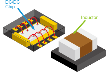
TOREX’s "micro DC/DC" converter XCL Series products focus on single-output switching regulators with an integrated control IC and coil.
The package construction is determined taking into consideration the product specifications, IC, coil, and heat generation (dissipation) among other factors.
Each package construction has its advantages and disadvantages. (See Table 1)
| Structure Name | Pocket Type | Stack Type | Multiple Type | Cool Post Type |
|---|---|---|---|---|
| Drawing | 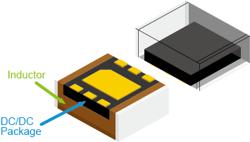 |
 |
 |
 |
| Description | The IC is covered by the coil. | The IC is stacked on the coil. | The IC and coil are placed side-by-side. | The molded IC is stacked under the coil. |
| Features * | ◎ Radiated noise ◎ Near magnetics field △ Cost ◎ Mounting area ○ Large current ○ Heat dissipation |
○ Radiated noise △ Near magnetics field ◎ Cost ○ Mounting area △ Large current △ Heat dissipation |
○ Radiated noise ○ Near magnetics field ○ Cost △ Mounting area ◎ Large current ◎ Heat dissipation |
○ Radiated noise ○ Near magnetics field ○ Cost ○ Mounting area ○ Large current ◎ Heat dissipation |
| Products | XCL100/XCL101 (step-up) XCL102/XCL103 (step-up) XCL201/XCL202 (step-down) XCL205/XCL206 (step-down) XCL210(step-down) XCL232(step-down) XCL233(step-down) XCL239/XCL240(step-down) XCL241/XCL242(step-down) |
XCL208/XCL209 (step-down) | XCL211/XCL212 (step-down) XCL237/XCL238(step-down) XCL243/XCL244(step-down) |
XCL104/XCL105 (step-up) |
- Pocket Type
IC package and coil are adhered together.
This shortens the switching current path and produces very little noise.
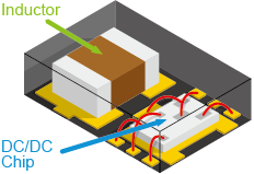
- Stack Type
This is a plastic mold that mounts the IC chip on the coil.
General-purpose coils are used making this type relatively inexpensive.
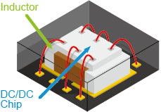
- Multiple Type
This is a plastic mold that places the coil and IC chip next to each other.
This provides good heat dissipation from the IC and coil, so this package is optimum for high currents.
- Cool Post Type
A copper post passes through the plastic mold to connect the coil on top to the circuit board with low resistance and low thermal resistance.
This achieves high efficiency and high heat dissipation regardless of the stack configuration.
3.Package construction optimal for low EMI
To obtain sufficient performance from the electrical devices, it is important to take into consideration noise from the circuit design stage to suppress the generation of noise. Component selection is done last, however, regardless of the fact that the power supply circuit is a source of noise generation. If the design of the power supply circuit is poor, the expected performance cannot be obtained no matter how high the performance of the IC or LSI used.
TOREX’s "micro DC/DC" converters
have various measures to achieve low EMI.
・Uses coils with low magnetic flux leakage
・Optimized coil characteristics for use with "micro DC/DC" converters
・Optimized DC/DC converter operation
・Pin position and construction take current path into consideration
3-1. EMI (Electromagnetic Interference)
Following is a comparison of the radiation noise of the two products XC9236B18D and XCL206B183.
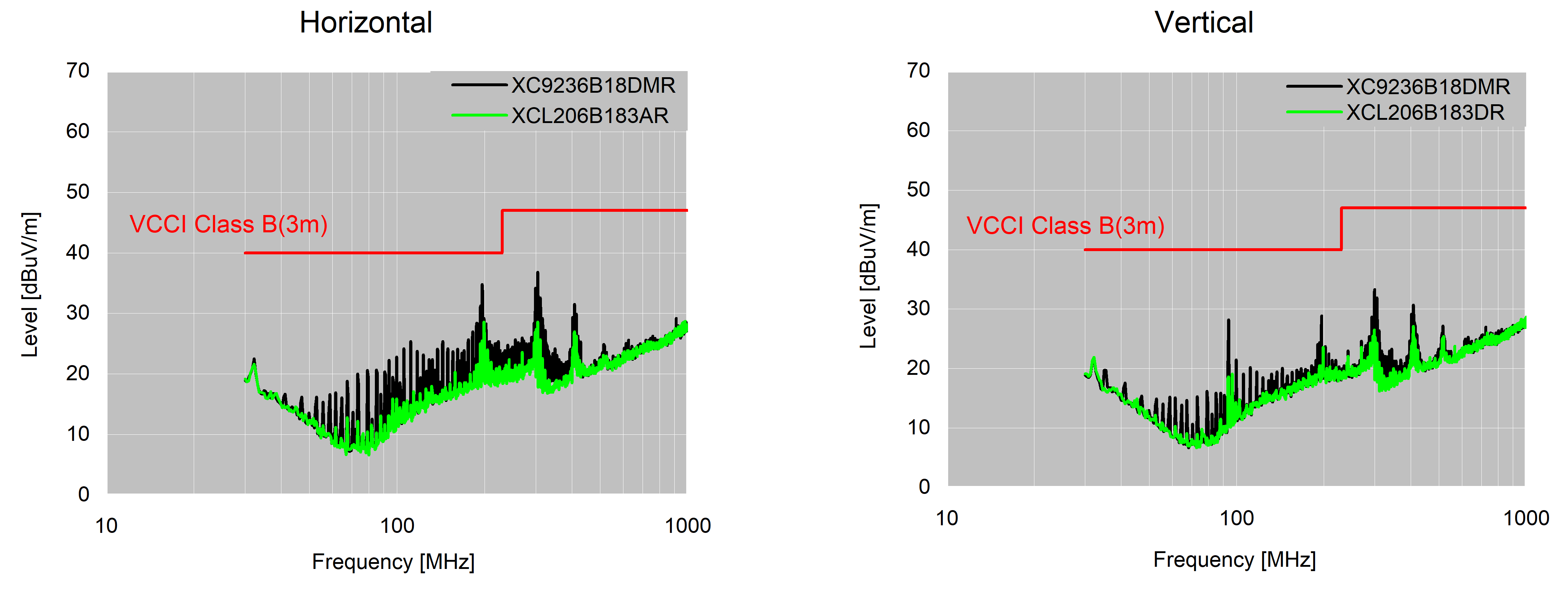
Fig. 1. XC9236B18D (fosc=3MHz) vs. XCL206B183 (fosc=3MHz) radiation noise
Here, XC9236 (black waveform) generates noise in the wide range of 50MHz-300MHz. We can see that XCL206 (green waveform), on the other hand, has a very low noise level. This shows there is a clear difference between the two despite them having the same operating frequency. For this reason, the XCL206 micro DC/DC converter is easy to use as a countermeasure for noise that has been left unresolved until late in the design process.
In addition, XCL202 (fosc=1.2MHz), which has the same construction as XCL206, has a low operating frequency, and thus even lower noise. (Refer to <Reference material> EMI data)
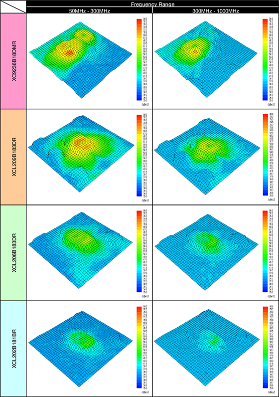
3-2. Near magnetic field strength
Following is a comparison of the near magnetic field strength of the two products XC9236B18D and XCL206B183.
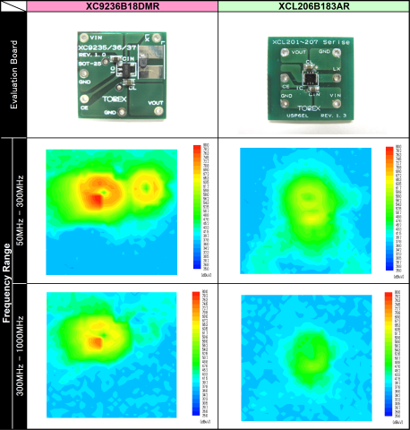
Fig. 2. XC9236B18D (fosc=3MHz) vs. XCL206B183 (fosc=3MHz) near magnetic field strength
XC9236 has a frequency range of 50MHz-300MHz, which is shown by the orange and red rings around the IC. We can see that the strongest noise is in the vicinity of the GND terminal. Yellow ring-shaped noise can also be seen at the coil. The coil is a simple shielded type (plastic mixed with ferrite powder) and the magnetic flux leakage is showing up as noise. On the other hand, there is no orange or red color for XCL206 showing that it generates little noise.
4.TOREX’s "micro DC/DC" can be used as if it is a regulator
The "micro DC/DC" converter can be used for switching even without a deep knowledge of power supplies, so the DC/DC converter can be used as if it were an LDO.
The efficiency and heat generation can be greatly reduced compared to using an LDO.
Further, the main peripheral components are just an input capacity and an output capacity, so the DC/DC converter can be configured in a small size the same as for an LDO.
4-1. Small size, low profile
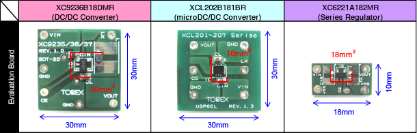
The "micro DC/DC" converter requires half the mounted space of a conventional DC/DC converter, which is configured as a discrete component, which lowers circuit board cost. This means a circuit board space the same size as that for a series regulator is sufficient. (Fig. 3)
4-2. Efficiency and component temperature
There is a large difference in power conversion efficiency between a series regulator and a "micro DC/DC" converter. (Fig. 4)
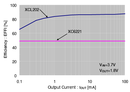
Ex: XC6221 … 48% (@IOUT=100mA)
XCL202 … 87% (@IOUT=100mA)
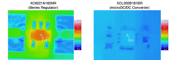
This difference in efficiency creates a large difference in a device’s battery operation time. This difference in efficiency is also power loss that is converted into heat in the IC. (Fig. 5)
XC6221 (SOT-25 package) ⇒ 61.3℃ (@Ta=23.4℃)
XCL202 (CL-2025 package) ⇒ 36.3℃ (@Ta=23.4℃)
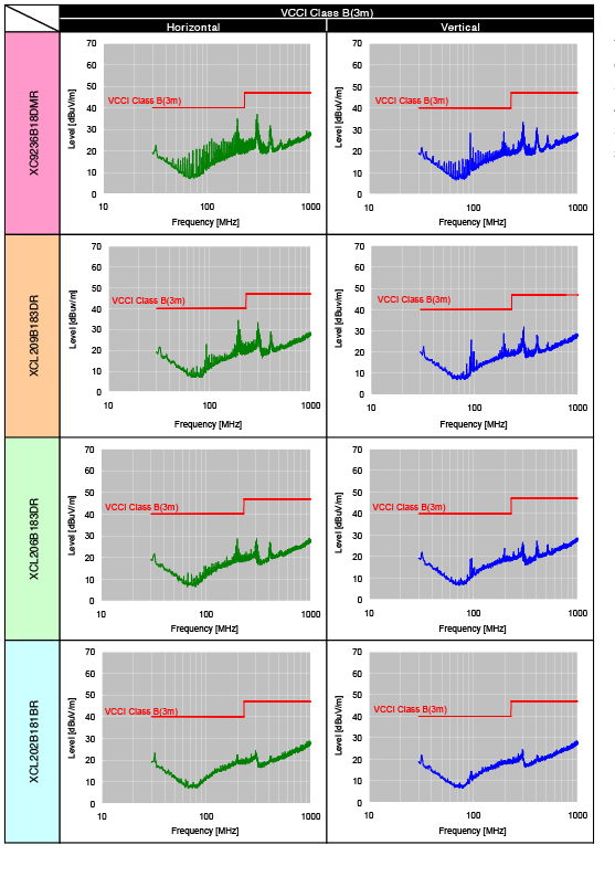
<Reference material> EMI (Electromagnetic Interference) VIN=3.7V, VOUT=1.8V, IOUT=200mA
<Reference Material>Near magnetic field strength VIN=3.7V, VOUT=1.8V, IOUT=200mA