
Push Button Load Switches to Preserve Battery Life
Recommended Applications

- IoT devices
- Wearable devices
- Fully-wireless earphones
- Devices equipped with buttons
- Devices with non-removable batteries, etc.
Features
| Input Voltage Rang | 1.8V〜6.0V(6.6V) |
|---|---|
| Turn-Off state (Quiescent Current) | 0.001μA(Typ.) |
| TTurn-On state (Quiescent Current) | 0.13μA(Typ.) |
| Turn-On Delay Time | 0.2s、1.0s、3.0s、5.0s |
| Turn-Off Method | Type A: Press and hold down the button & SHDN pin Type B:SHDN pin |
| Operating Ambient Temperature | -40℃ 〜 85℃ |
Package
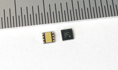
2.0mm x 2.0mm h:0.33mm
Function & Option
| XC6193 | External MOSFET Control function (GATE pin) |
|---|---|
| XC6194 | Power Good Output pin (PG pin) |
| XC6193A/XC6194A | Can be turned ON or OFF by pressing and holding down the button |
| XC6193B/XC6194B | Can be turned ON but not OFF by pressing and holding down the button |
| Added function | Output capacity discharge function Inrush current limiting function Output short circuit protection Self-heating protection function(Thermal shutdown) Input Voltage UVLO function |
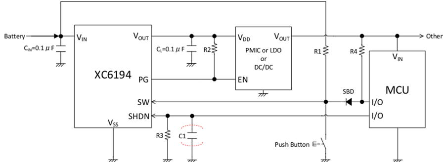
Typical Application Circuit
Shipment Mode (Ship Mode, Storage Mode) Reduces Power Consumption during Shipment from Factory!
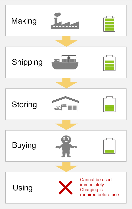
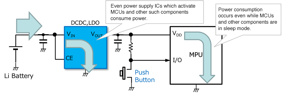
When XC6193/XC6194 is not used
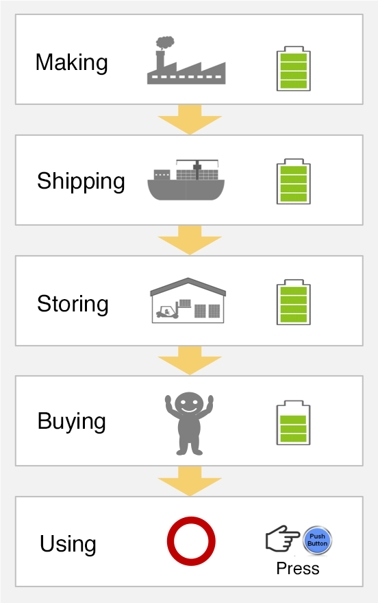
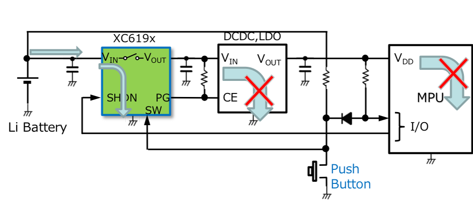
When XC6193/XC6194 is used
Example Circuit for Shipment Mode (Ship Mode, Storage Mode)
When XC6193/XC6194 is not used
Battery capacity: Case of 34mAh
Remaining capacity after 6 months of storage … Approx. 30%
When XC6193/XC6194 is used
Battery capacity: Case of 34mAh
Remaining capacity after 6 months of storage … Approx. 68%
For primary batteries … Approx. 99.5%
The downstream part of the battery is cut off by the XC6193/XC6194.
Quiescent current is for the XC6193/XC6194 only (IQ=0.001μA)
Using an XC6193/XC6194 can reduce
the quiescent current during OFF
status to less than 1/1000
Example Flow for Shipment Mode (Ship Mode, Storage Mode)
When XC6193/XC6194 is used
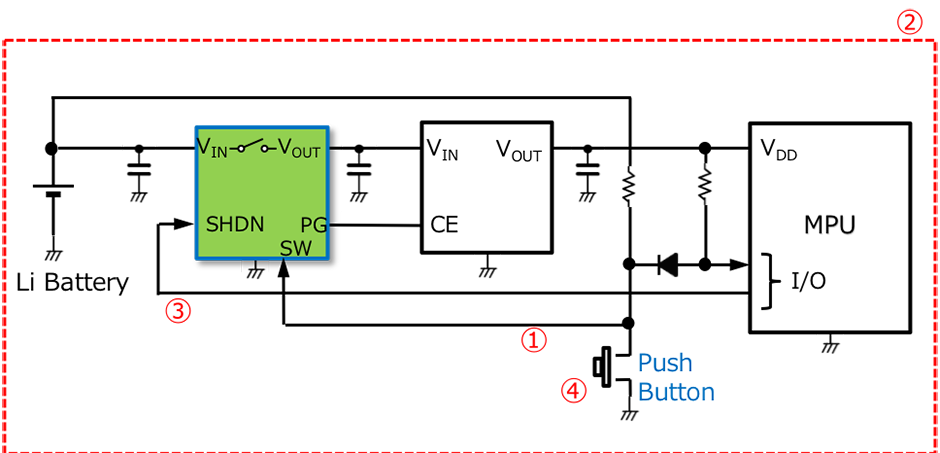
- ① After mounting, input "L" signal to SW terminal.
→ XC6193, XC6194 SW-ON - ② Perform shipping inspection.
- ③ After final processing in shipping inspection is complete, input "H" signal to SHDN terminal from MCU,etc.
→XC6193、XC6194 SW-OFF - ④ Upon delivery to user, user presses push button.
→ XC6193、XC6194 SW-ON
※1.The XC6193A and XC6194A can be turned ON or OFF using the SW terminal.
※2.The XC6193B and XC6194B can be turned ON using the SW terminal, but OFF only using the SHDN terminal.
※3.The XC6193 and XC6194 series are equipped with Turn-On delay times in preparation for unexpected noise during storage or transportation.
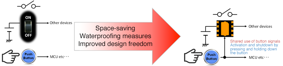
Can be Substituted for Physical Power Supply Switches!
Space-saving / Waterproof Properties / Greater Design Freedom
Safety Level not Found in Discrete or Physical Switches
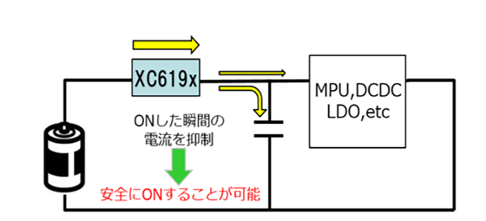
Inrush current limiting function
Suppresses the excessively high (higher than required) current which is applied at the moment it is switched ON
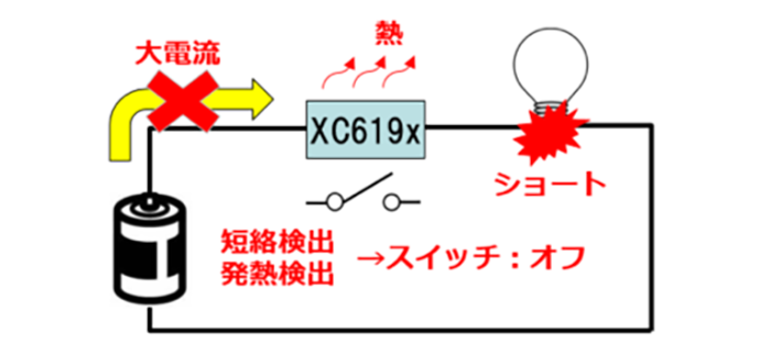
Protection against output short-circuits and heat generation
Detects short-circuits or heat generation and automatically switches OFF
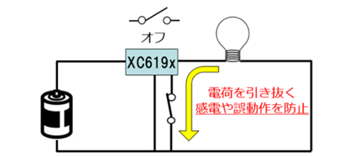
Discharge function
Draws out accumulated charge to prevent malfunctions
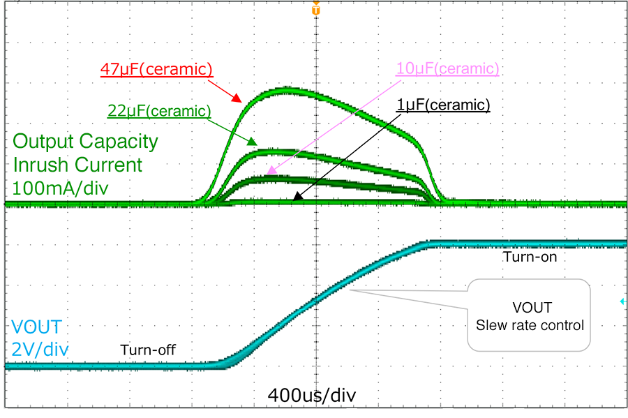
Also Effective as Load Switches Intended to Limit Inrush Current to Output Capacity
Output Capacity Inrush Current Properties
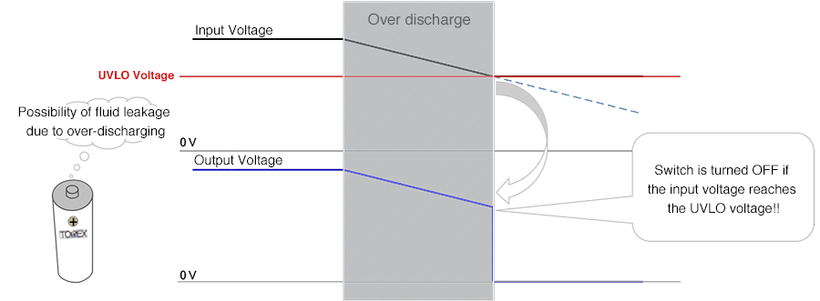
Effective as Measures to Prevent Fluid Leakage from Alkaline or Other Batteries!!
Reasons for Battery Fluid Leakage
Generally, if an alkaline or other battery is continuously over-discharged, gas produced by chemical reactions accumulates in the battery interior, and it is believed that if this gas builds up pressure and is emitted, a fluid leak will occur at the same time.
Over-discharging of batteries, the primary cause of fluid leakage, can be partially prevented by the input voltage UVLO function of this IC. If the battery voltage falls below a specified value due to continued over-discharging, this function will switch the power supply from an ON to OFF state, and eliminate the over-discharging condition.
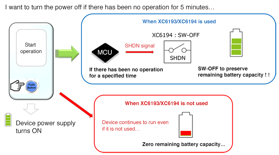
Push Button Intelligent Load Switch Application/Utilization Example 1
Implementation of Automatic Turn-OFF Function
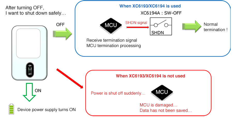
Push Button Intelligent Load Switch Application/Utilization Example 2
Termination Processing to be Performed before Turning OFF
Details of Push Button Load Switches
-
Low voltage operation, external FET
-
Low voltage operation, large current handling